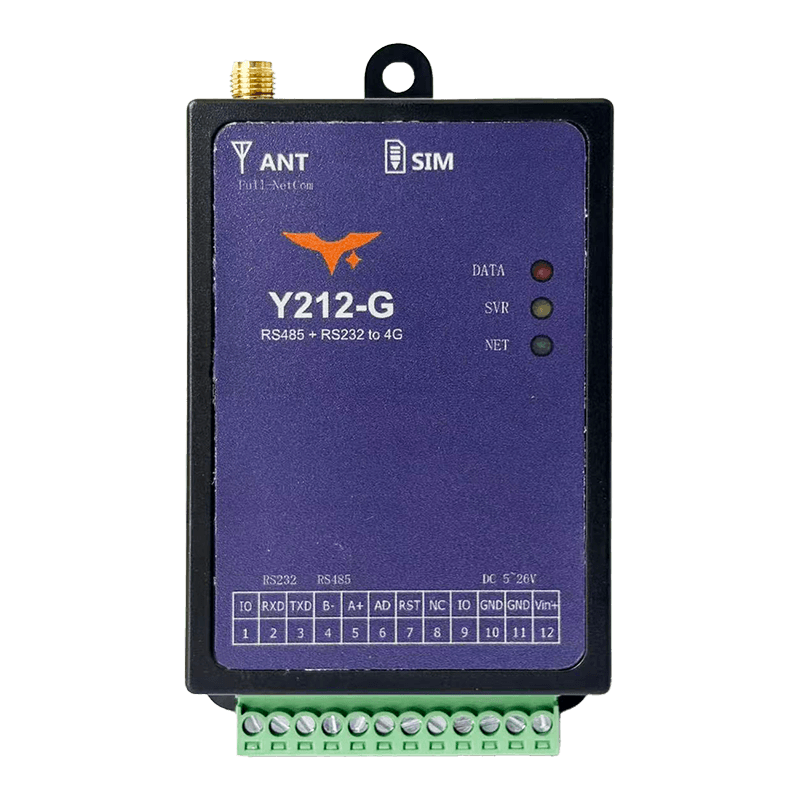
Appearance
Y212-G 4G Serial Gateway Specification
Reference: Y212-G / Y212-GWR Technical Manual
| Y212-G |
|---|
Contents
- Overview
- Ordering Information
- Key Features
- Technical Specifications
- Interfaces and Pin Definitions
- Mechanical and Environmental
- Installation and Wiring
- Important Notes
1. Overview
Y212-G is an industrial serial-to-4G gateway designed to bring RS232 and RS485 devices online quickly. With a built-in global LTE module, SIM slot, and SMA antenna interface, it enables plug-and-play data collection, transparent transmission, remote configuration, OTA upgrade, and alarm reporting without changing legacy field wiring.
It is well suited for PLCs, meters, sensors, pump stations, distribution cabinets, and other remote serial assets that need stable cellular backhaul and low-maintenance deployment.
| Item | Description |
|---|---|
| Product Type | Industrial 4G serial gateway |
| Cellular Uplink | Global LTE Cat.4, Cat.1 compatible |
| Serial Interface | RS232 + RS485 |
| Local I/O | 2 x GPIO plus 1 x 0 to 8 V analog input |
| Power Input | 5 to 28 VDC, optional 6 to 65 VDC wide-range version |
| Typical Use | Serial-to-cloud connectivity, remote maintenance, and field data collection |
Highlights
- Global 4G coverage for cross-region deployments
- RS232 and RS485 in one device for easier field integration
- Built-in GPIO and analog input for simple local signal collection
- OTA, logs, and remote diagnostics reduce on-site maintenance
- Compact design supports both panel and DIN-rail installation
Typical Applications
- Smart agriculture: Collect data from temperature, humidity, and irrigation sensors and upload it to the cloud
- Industrial automation: Connect legacy PLCs and meters to cloud platforms over RS485 for remote diagnostics
- Energy monitoring: Report status and alarms from distribution rooms and PV inverters
- Environmental monitoring: Aggregate data from weather and water-quality sensors at remote stations
2. Ordering Information
2.1 Model Naming
text
Y212 - G
  |     \- G: 4G / 5G cellular communication family, including LTE Cat.1
  \------- Y212: Y2 series serial data collection terminal
2.2 SKU and Configuration
| SKU | Description | Network Bands | Power Range |
|---|---|---|---|
| Y212-G | Qualcomm Cat.4 global serial gateway, RS232 + RS485, 2 x IO, 1 x AD, remote maintenance support | Global 4G, 7 modes and 15 bands: LTE-FDD B1/B2/B3/B4/B5/B7/B8/B12/B13/B17/B20/B25/B26/B28; LTE-TDD B34/B38/B39/B40/B41; WCDMA B1/B2/B5/B8; CDMA2000 BC0; GSM EGSM900/DCS1800/PCS1900 | 5 to 28 VDC, optional wide-range version 6 to 65 VDC |
2.3 Package Contents
- Y212-G main unit x1
- 4G omnidirectional antenna, SMA x1
- SIM eject pin x1
- DIN-rail clip, optional x1
- Quick-start card and warranty card
2.4 Optional Accessories
- USB-to-RS485 debug cable
12/24 VDCindustrial power adapter- Lightning protection kit and shielded twisted pair cable
3. Key Features
- Global 4G Cat.4: One device supports major global LTE bands for fast international deployment.
- RS232 + RS485 in One Box: Connect common serial devices without adding external converters.
- Cloud-Ready Protocols: Supports TCP, UDP, HTTP, HTTPS, MQTT, MQTTS, and WebSocket.
- Remote OTA and Diagnostics: Configure, upgrade, and troubleshoot devices without site visits.
- Built-In I/O and Analog Input:
2 xGPIO plus1 x 0 to 8 Vinput support local status collection. - Wide Input, Industrial Protection:
5 to 28 VDCstandard or6 to 65 VDCwide-range input with surge and reverse-polarity protection. - Flexible Online Modes: Always-online, wake-up, on-demand, and scheduled modes fit different response and power needs.
- Compact Industrial Installation: Panel or
35 mmDIN-rail mounting speeds up cabinet deployment.
4. Technical Specifications
4.1 Wireless and Network
| Parameter | Specification |
|---|---|
| Cellular Module | Qualcomm LTE Cat.4, Cat.1 compatible, backward-compatible with GPRS and EDGE, multiple hardware watchdogs |
| Radio Modes | Global, 7 modes and 15 bands: LTE-FDD B1/B2/B3/B4/B5/B7/B8/B12/B13/B17/B20/B25/B26/B28; LTE-TDD B34/B38/B39/B40/B41; WCDMA B1/B2/B5/B8; CDMA2000 BC0; GSM EGSM900/DCS1800/PCS1900 |
| Protocol Stack | TCP, UDP, HTTP, HTTPS, MQTT, MQTTS, WebSocket |
| SIM | Drawer-style 1.8 V / 3 V SIM or USIM, full-size card |
| Antenna Interface | 50 ohm SMA female, supports 4G and GNSS coexistence antennas |
| GNSS Positioning | Optional BeiDou plus GPS module with serial and server-side output |
4.2 Communication Interfaces
| Parameter | Specification |
|---|---|
| Main Serial Port | RS232 + RS485, shared terminal, 1200 to 921600 bps, default 9600-8-N-1 |
| Secondary UART | TTL 3.3 V / 5 V, supported on some hardware revisions |
| GPIO | 2 x, configurable as input or output, 3.3 V or 1.8 V logic |
| Analog Input | 1 x 0 to 8 V, default input impedance >100 kohm |
| USB | Available through a debug cable for PC configuration, optional accessory |
4.3 Electrical and Power Consumption
| Parameter | Specification |
|---|---|
| Supply Voltage | 5 to 28 VDC, standard version; 6 to 65 VDC, wide-range version |
| Recommended Power | Power adapter rated >=2 A |
| Typical Consumption | Online idle 20 to 40 mA @ 12 V; data transmission 60 to 100 mA @ 12 V; GNSS adds about 30 to 40 mA |
| Protection | Reverse-polarity protection, over-voltage protection, surge protection, hardware and software watchdog |
4.4 Input and Output Capability
| Parameter | Specification |
|---|---|
| IO1 / IO2 | Configurable through GPI / GPO commands, input or output mode selectable |
| AD Range | 0 to 8 V; for best linearity, 0 to 6 V is recommended |
| Sampling Mode | Periodic sampling or command-triggered sampling, with data forwarded to the server |
4.5 Environmental
| Parameter | Specification |
|---|---|
| Operating Temperature | -40 to 85 C |
| Storage Temperature | -45 to 90 C |
| Relative Humidity | 5 to 95% RH, non-condensing |
| Altitude | <= 2000 m |
| Reliability | MTBF > 200,000 h, typical |
5. Interfaces and Pin Definitions
5.1 Terminal Definition
| Pin | Signal | Description |
|---|---|---|
| 1 | IO1 | Configurable digital input or output, high level 3.3 V or 1.8 V |
| 2 | 232-RX | Connect to external device TX, RS232 input |
| 3 | 232-TX | Connect to external device RX, RS232 output |
| 4 | 485B- | RS485 differential B- |
| 5 | 485A+ | RS485 differential A+ |
| 6 | AD | 0 to 8 V analog input |
| 7 | R2-TTL | Secondary UART RX2 on Qualcomm version |
| 8 | T2-TTL | Secondary UART TX2 on Qualcomm version |
| 9 | IO2 | Configurable digital input or output |
| 10 | GND | System ground |
| 11 | GND | System ground, paralleled with pin 10 |
| 12 | Vin+ | DC positive input, 5 to 28 V standard or 6 to 65 V wide-range |
5.2 Interface Summary
| Interface | Description |
|---|---|
| Power Terminal | 3.5 mm pluggable 12-pin terminal, recommended 14 to 24 AWG wire, external 2 A fast fuse suggested |
| SIM Slot | Drawer-style full-size SIM, push-to-eject with lock support |
| Antenna Port | SMA female, use 4G omnidirectional or directional antenna with good grounding |
| LEDs | Net, Server, and Data/GPS indicators show network and data status |
| Reset Button | Press 3 to 5 s for soft reset; press >10 s to restore factory parameters |
5.3 LED Status
| LED | Status | Description |
|---|---|---|
| Net | Off | Network not registered |
| Net | 64 ms on / 3 s off | Registration failed, retrying |
| Net | 64 ms on / 1 s off | Network registered, waiting for server |
| Net | 64 ms on / 300 ms off | Network link established |
| Server | Off | Not connected to center server |
| Server | On | Connected to center server |
| Data/GPS | Off | No data activity or GNSS disabled |
| Data/GPS | Blinking | Data TX/RX active or GNSS searching satellites |
| Data/GPS | On | GNSS fix acquired on positioning version |
6. Mechanical and Environmental
| Item | Specification |
|---|---|
| Housing Material | Metal enclosure or ABS DIN-rail enclosure, UL94 V-0 flame retardant |
| Standard Dimensions | 80 x 63.8 x 21.3 mm, DIN-rail version |
| Mounting | 35 mm DIN rail, panel screws, or double-sided adhesive |
| Weight | About 180 g, including housing and terminal |
| Protection Rating | IP20, indoor installation |
| Cooling Clearance | Top and bottom >=15 mm, left and right >=10 mm, front >=40 mm |
7. Installation and Wiring
- Install the antenna: Confirm the supplied 4G or GNSS antenna model, tighten it clockwise to the SMA connector, keep it vertical, and avoid metal obstruction.
- Insert the SIM card: Use the included tool to press the yellow eject button, place an activated IoT SIM in the tray, and push it back in.
- Wire the power input: Connect GND to pin 11 and DC positive to pin 12. Verify polarity and voltage range before power-up. An external
2 Afuse is recommended. - Connect the serial port: Use RS232 on pins 2 and 3 or RS485 on pins 4 and 5. Use shielded twisted pair and proper grounding. If a secondary TTL UART is required, connect pins 7 and 8.
- Connect IO and analog signals: Wire dry or wet contacts to IO1 and IO2 as needed and keep the analog signal within
0 to 8 V. - Mount the device: Snap it onto a
35 mmDIN rail or secure it with screws to prevent loosening in vibration-prone environments. - Power on and commission: Check the Net, Server, and Data/GPS LEDs, then complete parameter configuration and connectivity testing through the serial port or remote platform.
8. Important Notes
- Power Requirements: Use a stable DC power source with sufficient current margin to avoid voltage drop caused by shared high-power loads.
- Antenna Separation: 4G and GNSS antennas are not interchangeable. Keep at least
30 cmapart and ensure proper grounding. - Data Security: HTTPS and MQTTS are optional. They must be enabled on the platform side with correct certificate configuration.
- Firmware Upgrade: Perform OTA only on a stable network and never power off during upgrade.
- Lightning Protection: In outdoor or high-surge environments, use surge protection and proper grounding to protect the communication interfaces.
- Manufacturer: Hunan YenGear Tech Co., Ltd.
- Address: Room 21014, Building 1, Fudi Xingguang Tiandi, Yingxin Road, Yuhua District, Changsha, Hunan, China
- Email: hi@yengear.com
- Website: www.yengear.com