Appearance
Y301-220/222 I/O Module Specification
| Y301-220 | Y301-222 |
|---|---|
 |  |
Contents
- Overview
- Ordering Information
- Key Features
- Technical Specifications
- Interfaces and Pinout
- Mechanical and Environmental
- Automation Rules
- Modbus Address Quick Map
1. Overview
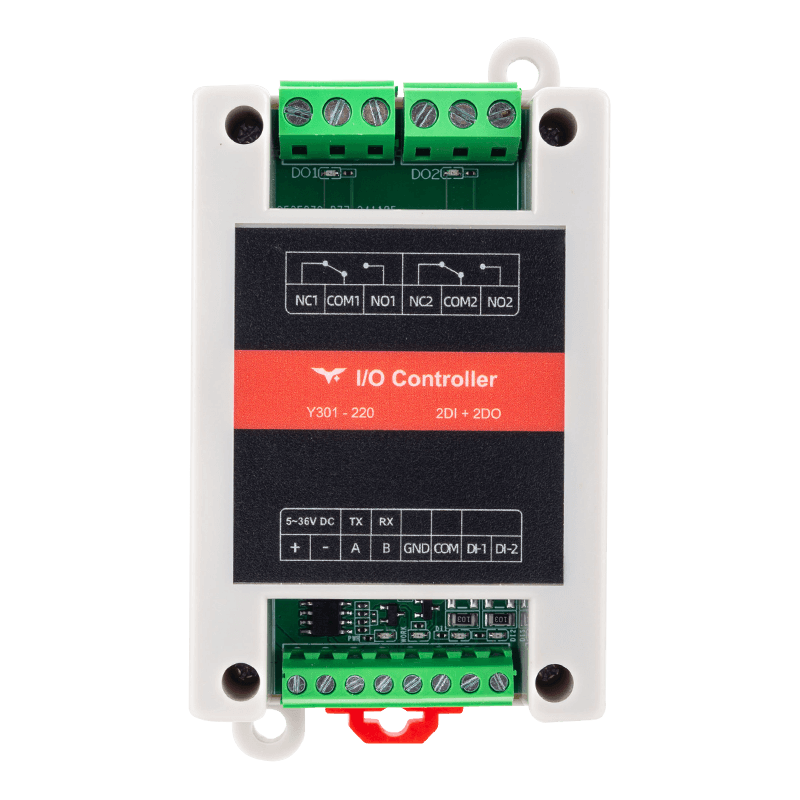
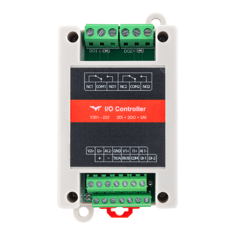
The Y301-220/222 are high-power serial I/O expansion modules that combine opto-isolated digital inputs, 10 A relay outputs, and, on the Y301-222, dual analog inputs for 0-10 V or 4-20 mA sensing.
Both models support Modbus RTU over RS485, RS232, or TTL and can be integrated with PLCs, SCADA systems, and industrial gateways.
| Model | Digital Input | Digital Output | Analog Input | Typical Role |
|---|---|---|---|---|
| Y301-220 | 2 | 2 x SPDT | - | Equipment monitoring and control |
| Y301-222 | 2 | 2 x SPDT | 2 (0-10 V / 4-20 mA) | Process monitoring and control |
Analog input is available on the Y301-222 only.
Product Highlights
- 82 x 54 x 32 mm enclosure with DIN-rail and screw mounting options
- 277 VAC / 10 A relay contacts for HVAC, lighting, and pump control
- Built-in automation engine with local rules, DO retention, and DIP address offset
2. Ordering Information
2.1 Model Naming
Y301-XYZ
- XYZ: function combination (
220 = 2DI + 2DO + 0AI,222 = 2DI + 2DO + 2AI)
2.2 Interface Options
All models are available with the following serial interfaces:
| Interface | Description |
|---|---|
| RS485 | Standard version for Modbus RTU multi-drop networks |
| RS232 | Optional version for point-to-point communication |
| TTL | Optional on selected models for direct MCU integration |
2.3 Ordering Table
| SKU | Description |
|---|---|
| Y301-220 | 2 DI + 2 DO, high-power relay module |
| Y301-222 | 2 DI + 2 DO + 2 AI, combo I/O module |
2.4 Standard Package
1 x Y301 module, digital quick reference guide, and warranty card.
Optional accessories include a USB-to-RS485 converter, DIN clip, power supply, and shielded cable set.
3. Key Features
- High-power relay outputs - 277 VAC / 10 A or 28 VDC / 10 A silver-alloy contacts
- Opto-isolated DI with pulse counting - Rising/falling edge capture with configurable debounce from 5 to 255 ms
- Analog input on Y301-222 - Two channels supporting 0-10 V or 4-20 mA, 16-bit resolution, and +/-1% FS accuracy
- Automation engine - Up to 4 local rules covering follow, pulse, delay, schedule, cycle, AI threshold, and logic modes
- Output retention and addressing - Configurable retention plus 5-bit DIP offset on top of the software address
- Industrial design - 5-36 VDC input, -40 to +85 C operation, hardware watchdog, and Reload button
4. Technical Specifications
4.1 Electrical and Environmental
| Parameter | Specification |
|---|---|
| Supply voltage | 5-36 VDC |
| Typical current | 150 mA @ 12 V (all DO off) |
| Maximum current | 200 mA @ 12 V (two relays on + AI sampling) |
| Operating temperature | -40 to +85 C |
| Humidity | 5-95% RH, non-condensing |
| Altitude | <= 2000 m |
4.2 Digital Input (2 channels)
| Item | Specification |
|---|---|
| Type | Dry/wet contact, opto-isolated |
| Voltage range | 5-36 V (wet contact mode) |
| Input current | <5 mA per channel |
| Sampling rate | 100 Hz |
| Pulse counter | 32-bit, selectable rising/falling edge |
| Debounce | 5-255 ms (default 50 ms) |
4.3 Digital Output (2 x SPDT relays)
| Item | Specification |
|---|---|
| Contact rating | 277 VAC 10 A / 28 VDC 10 A |
| Minimum load | 10 VAC 10 mA |
| Switching time | <10 ms operate / <5 ms release |
| Electrical life | 100k cycles at rated load |
| Output retention | None / soft reboot / power-cycle retention |
4.4 Analog Input (Y301-222, 2 channels)
| Item | Specification |
|---|---|
| Input type | 0-10 V or 4-20 mA, configurable per channel |
| Resolution | 16-bit |
| Accuracy | +/-1% FS |
| Sampling rate | 10 Hz |
| Input impedance | Voltage mode: >100 kohm; current mode: 250 ohm |
| Overvoltage protection | +/-30 V |
4.5 Communication
| Item | Specification |
|---|---|
| Interface | RS485 (2-wire), optional RS232 or TTL |
| Protocol | Modbus RTU slave |
| Supported function codes | 0x01, 0x02, 0x03, 0x04, 0x05, 0x06, 0x0F, 0x10 |
| Baud rate | 600-230400 bps (default 9600) |
| Addressing | Device address 1-255 + DIP offset 0-31 |
| Frame format | [slave][function][data][CRC low][CRC high] |
4.6 Factory Defaults
| Parameter | Default |
|---|---|
| Device address | 1 |
| Baud rate | 9600 |
| Data bits / Stop bits / Parity | 8 / 1 / None |
| Output retention | Soft reboot retention (0x0040 = 1) |
| Pulse count mode | Rising edge (0x0041 = 1) |
| Pulse debounce | 50 ms (0x0042 = 50) |
5. Interfaces and Pinout
5.1 Terminal Overview
| Group | Description |
|---|---|
| Power | V+, V- screw terminals + DC 5.5 x 2.1 mm jack |
| DIP switch | SW1-SW5 (binary address offset) |
| Reload | Hold 3-15 s to restore factory defaults |
| DI | COM+, COM-, DI1-DI2 |
| DO | NCn / COMn / NOn for channels 1-2 |
| AI (222 only) | AI1+, AI1-, AI2+, AI2- |
| Communication | A/B/GND (RS485) or TX/RX/GND (RS232/TTL) |
5.2 Wiring Guidelines
- Use 20-16 AWG power wiring with a 1 A upstream fuse.
- For dry-contact DI, bridge
COM+to the targetDIthrough the external contact. - For wet-contact DI, connect the external 5-36 V reference to
COM-. - For relay outputs driving inductive loads, add an RC snubber for AC loads or a flyback diode for DC loads.
- For Y301-222 analog input wiring, connect the source directly in voltage mode and use the current loop terminals in current mode.
- For RS485, use shielded twisted pair, terminate both ends with 120 ohm resistors, and keep a common reference ground.
6. Mechanical and Environmental
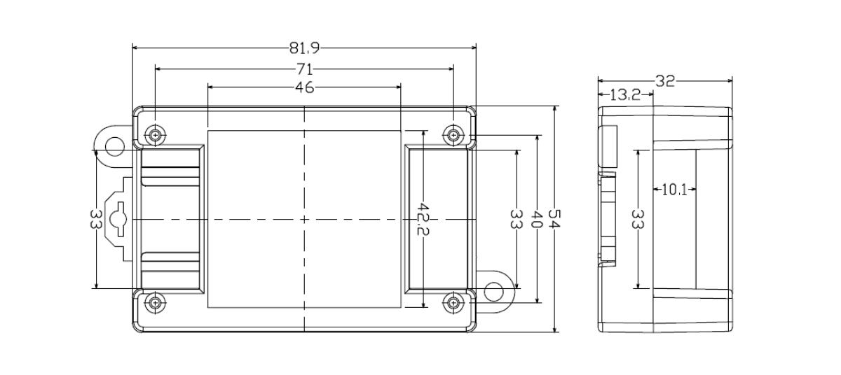
| Item | Value |
|---|---|
| Dimensions | 82 x 54 x 32 mm |
| Mounting | 35 mm DIN clip or screw slots |
| Protection | IP20 |
| Housing | UL94 V-0 flame-retardant plastic |
Keep at least 15 mm clearance above and below, 10 mm on each side, and 40 mm in front for wiring and airflow.
7. Automation Rules
| Mode Group | Description |
|---|---|
| Follow | DI follow, DI inverse, delayed follow |
| Pulse / Delay | Pulse output, delayed control |
| Time-based | One-shot schedule, cyclic schedule, daily schedule, startup delay action |
| AI threshold (222) | AI voltage high/low, AI current high/low |
| Logic | AND / OR / XOR |
| Others | Button mode, periodic cycle |
- Up to 4 rules total (2 rules per DO channel)
- Rule register base is
0x0080, each rule occupies 8 registers (16 bytes) - Rules execute locally without host polling
- If multiple rules conflict, later rules take priority
8. Modbus Address Quick Map
This section uses Modbus addresses only (0xXXXX), not PLC addresses.
8.1 DI / DO / AI
| Type | Channel | Modbus Address | Access |
|---|---|---|---|
| DI | DI1 | 0x0000 | RO |
| DI | DI2 | 0x0001 | RO |
| DO | DO1 | 0x0000 | RW |
| DO | DO2 | 0x0001 | RW |
| AI (222) | AI1 voltage | 0x0000 | RO |
| AI (222) | AI1 current | 0x0001 | RO |
| AI (222) | AI2 voltage | 0x0002 | RO |
| AI (222) | AI2 current | 0x0003 | RO |
8.2 Key Holding Registers
| Address | Name | Access | Notes |
|---|---|---|---|
0x002A | Running slave address | RO | Device address + DIP offset |
0x002B | DIP offset address | RO | 0-31 |
0x003E | Device address | RW | 1-255 |
0x003F | Broadcast mode | RW | 0/1/2 |
0x0040 | Output retention mode | RW | 0/1/2 |
0x0041 | Pulse count edge mode | RW | 0=falling, 1=rising |
0x0042 | Pulse debounce (ms) | RW | 5-255 |
0x0055 | RTC time (Unix) | RW | 32-bit |
0x0057 | Baud rate | RW | 32-bit |
0x0059 | Data bits | RW | 8/9 |
0x005A | Stop bits | RW | 1/2 |
0x005B | Parity | RW | 0=None, 1=Odd, 2=Even |
8.3 Counters, Rule Blocks, and Special Register
| Address | Name | Notes |
|---|---|---|
0x0500 | DI1 counter | 32-bit, write 0 to clear |
0x0502 | DI2 counter | 32-bit, write 0 to clear |
0x0080 | Rule block 1 | 8 registers per rule |
0x0088 | Rule block 2 | 8 registers per rule |
0x0090 | Rule block 3 | 8 registers per rule |
0x0098 | Rule block 4 | 8 registers per rule |
0x0800 | Special register | 0x5500 reboot, 0x0055/0x5555 factory reset + reboot |
- Manufacturer: Hunan YenGear Tech Co., Ltd.
- Address: Room 21014, Building 1, Fudi Xingguang Tiandi, Yingxin Road, Yuhua District, Changsha, Hunan, China
- Email: hi@yengear.com
- Website: www.yengear.com