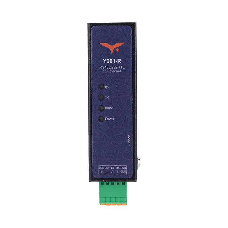
Appearance
Y201-R Mini Ethernet DTU Specification
Reference: Y201-R Technical Manual
Contents
- Overview
- Ordering Information
- Key Features
- Technical Specifications
- Interfaces and Indicators
- Installation and Access
- Application Notes
1. Overview
Y201-R is the Ethernet model in the Y201 mini DTU family. It bridges serial devices to Ethernet networks and uses a dual-core 240 MHz MCU, 5 to 36 VDC wide-range power input, and selectable RS485, RS232, or TTL serial interfaces. The device provides two Socket channels for network communication.
It supports TCP and UDP transparent transmission, HTTP client, MQTT client, and Modbus RTU to Modbus TCP conversion. Typical applications include industrial data acquisition, building control, energy metering, and serial device retrofit projects.
| Item | Description |
|---|---|
| Positioning | Serial-to-Ethernet industrial DTU |
| Processor | Dual-core 240 MHz MCU |
| Supply Range | 5 to 36 VDC |
| Serial Interface | RS485 / RS232 / TTL, depending on SKU |
| Network Interface | RJ45 Ethernet |
| Configuration | Web UI in a browser |
Highlights
- Dual Socket channels A and B for multi-center data access
- Modbus RTU to Modbus TCP protocol conversion
- Registration packets, heartbeat packets, and auto-reconnect
- HTTP and MQTT cloud connectivity, including Alibaba Cloud MQTT mapping
- Browser-based configuration with no dedicated PC utility required
2. Ordering Information
2.1 Model Naming
Y201-R-IF
R: Ethernet uplink through RJ45IF: Serial interface type,485,232, orTTL
2.2 SKU List
| SKU | Serial Interface | Typical Application |
|---|---|---|
| Y201-R-485 | RS485 | Industrial bus and meter networking |
| Y201-R-232 | RS232 | Legacy serial device networking |
| Y201-R-TTL | TTL | Direct connection to embedded controller boards |
2.3 Standard Package
1 x Y201-R device, quick guide, warranty information.
Optional accessories: power adapter, serial cable harness, DIN mounting parts.
3. Key Features
- Dual-Socket Architecture: Each serial port maps to Socket A and B for main-link and backup-link separation.
- Broad Protocol Coverage: Supports TCP server/client, UDP server/client, HTTP client, and MQTT client.
- Modbus Gateway: Can switch between transparent mode and Modbus RTU to Modbus TCP conversion mode.
- Registration Packet Modes: Supports
FIRST,EVERY, andALL. - Heartbeat Keepalive: Supports both network heartbeat and serial heartbeat for online status monitoring.
- Auto Reconnect: TCP client reconnects automatically on connection failure, with about a
1 sretry interval. - Web-Based Maintenance: Default address
192.168.10.8, default loginadmin/admin.
4. Technical Specifications
4.1 Electrical and Hardware
| Parameter | Specification |
|---|---|
| Processor | Dual-core 240 MHz MCU |
| Supply Voltage | 5 to 36 VDC |
| Serial Interface | RS485 / RS232 / TTL, depending on model |
| Network Interface | RJ45 Ethernet |
4.2 Network and Protocol Capability
| Item | Specification |
|---|---|
| Socket A | TCP server / TCP client / UDP server / UDP client / HTTP client / MQTT client |
| Socket B | TCP client / UDP server / UDP client |
| TCP Server Concurrency | Up to 8 clients per port |
| TCP Client Behavior | Connects automatically after IP acquisition and reconnects on failure |
| HTTP | Supports HTTP 1.0 / 1.1, GET / POST / AUTO |
| MQTT | Supports standard MQTT and Alibaba Cloud MQTT format |
4.3 Gateway and Data Functions
| Item | Description |
|---|---|
| Modbus Gateway | Disabled by default; converts Modbus RTU and Modbus TCP when enabled |
| Registration Packet Modes | FIRST / EVERY / ALL |
| Heartbeat Direction | Network heartbeat for TCP/UDP client, serial heartbeat for serial side |
| AT-State Impact | Heartbeat transmission pauses while the device is in AT command mode |
5. Interfaces and Indicators
5.1 Hardware Interfaces
| Interface | Description |
|---|---|
| Power Input | Device power input |
| Serial Port | RS485 / RS232 / TTL, depending on SKU |
| RJ45 Port | Network access and debugging |
5.2 Status and Maintenance
- LEDs indicate power, runtime status, and data activity.
- The Web UI shows status, system information, and port configuration.
- Parameters must be saved and then applied by reboot.
6. Installation and Access
6.1 Initial Access
- Power on the device and connect the PC to the RJ45 port with an Ethernet cable.
- Set the PC NIC to the same subnet as the device.
- Open
192.168.10.8in a browser. - Log in with
admin/admin.
6.2 Configuration Recommendations
- Configure the device IP first and keep it on the same subnet as the host.
- Set serial parameters to match the field device.
- Select the required Socket protocol, such as TCP, UDP, HTTP, or MQTT.
- Enable Modbus gateway, registration packet, and heartbeat as needed.
- Save parameters and reboot the device.
6.3 Mechanical Dimensions
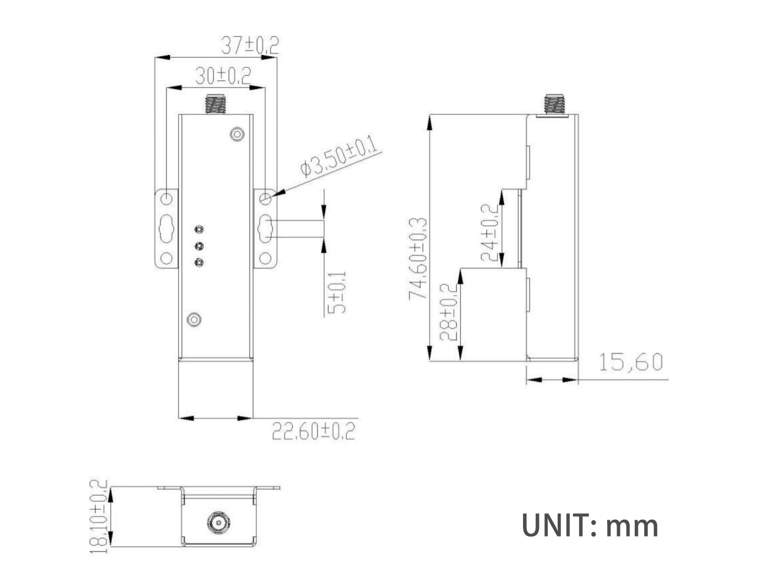
This dimension drawing applies to the Y201 mini enclosure and can be used as an installation reference for the Y201-R.
7. Application Notes
- Serial-to-Ethernet transparent transmission: Forward PLC, meter, and data logger serial data to a LAN or host system.
- Modbus retrofit: Enable gateway mode when the host uses Modbus TCP and the field device uses Modbus RTU.
- Cloud connectivity: Push serial data to business platforms through HTTP client or MQTT client.
- Dual-link architecture: Separate local monitoring and cloud upload with Socket A and B for better resilience.
For detailed configuration steps and protocol examples, see the Y201-R Technical Manual.
- Manufacturer: Hunan YenGear Tech Co., Ltd.
- Address: Room 21014, Building 1, Fudi Xingguang Tiandi, Yingxin Road, Yuhua District, Changsha, Hunan, China
- Email: hi@yengear.com
- Website: www.yengear.com