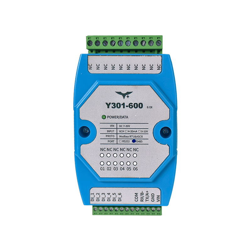
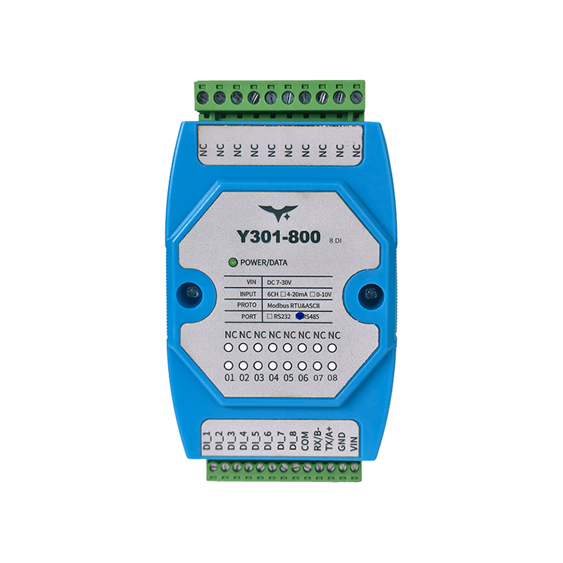
Appearance
Y301-600/800/G00 Digital Input Module Specification
| Y301-600 | Y301-800 | Y301-G00 |
|---|---|---|
 |  |  |
Contents
- Overview
- Ordering Information
- Key Features
- Technical Specifications
- Interfaces and Indicators
- Mechanical and Environmental
- Installation and Wiring
- Communication and Configuration
- Notes
1. Overview
The Y301-600/800/G00 are digital input modules in the Y301 family, designed for discrete signal acquisition. The modules use opto-isolated inputs and communicate with PLCs, industrial PCs, or edge gateways over Modbus RTU/ASCII.
The three models differ mainly in input channel count. Power, communication, and mounting specifications remain aligned across the platform.
| Model | DI | DO | AI | AO | Typical Application |
|---|---|---|---|---|---|
| Y301-600 | 6 | 0 | 0 | 0 | Small equipment status acquisition |
| Y301-800 | 8 | 0 | 0 | 0 | General cabinet switch monitoring |
| Y301-G00 | 16 | 0 | 0 | 0 | High-density point collection |
2. Ordering Information
2.1 Model Naming
Y301-<DI><DO><AI><AO>-<interface>
Y301-600:6DI + 0DO + 0AI + 0AOY301-800:8DI + 0DO + 0AI + 0AOY301-G00:16DI + 0DO + 0AI + 0AO
2.2 Interface Options
| Interface | Description |
|---|---|
| RS485 | Supports multi-drop bus networks |
| RS232 | Suitable for point-to-point connections |
2.3 SKU Examples
| SKU | Interface | Description |
|---|---|---|
| Y301-600-RS485 | RS485 | 6-channel opto-isolated digital input |
| Y301-600-RS232 | RS232 | 6-channel opto-isolated digital input |
| Y301-800-RS485 | RS485 | 8-channel opto-isolated digital input |
| Y301-800-RS232 | RS232 | 8-channel opto-isolated digital input |
| Y301-G00-RS485 | RS485 | 16-channel opto-isolated digital input |
| Y301-G00-RS232 | RS232 | 16-channel opto-isolated digital input |
2.4 Standard Package
Module, quick reference card, and warranty information. Optional accessories include a USB-to-RS485 converter, DIN-rail power supply, and shielded twisted-pair cable.
3. Key Features
- Opto-isolated DI inputs for industrial discrete signal acquisition
- Supports both dry contact and active voltage input (3.3-24 VDC)
- 7-30 VDC supply range for common 12 V and 24 V systems
- Supports both Modbus RTU and Modbus ASCII
- Available with RS485 and RS232 serial interfaces
- Supports device addressing from 0 to 255 and broadcast address 254
- Supports baud rate settings of 2400, 4800, 9600, 19200, and 38400 bps
- 35 mm DIN-rail mounting for standard cabinets
4. Technical Specifications
4.1 General Specifications
| Parameter | Specification |
|---|---|
| Supply voltage | 7-30 VDC |
| Data interface | RS485, RS232 |
| Protocol | Modbus RTU, Modbus ASCII |
| Default serial format | 9600, N, 8, 1 |
| Optional baud rates | 2400, 4800, 9600, 19200, 38400 bps |
| Address range | 0-255 (broadcast address 254) |
| Power indicator | 1 LED |
| Operating temperature | -40 to +85 C |
| Mounting | 35 mm DIN rail |
| Dimensions | 120 x 70 x 35 mm |
| Weight | Approx. 60 g |
4.2 Digital Input Specifications
| Parameter | Y301-600 | Y301-800 | Y301-G00 |
|---|---|---|---|
| DI channel count | 6 | 8 | 16 |
| Input type | Opto-isolated discrete input | Opto-isolated discrete input | Opto-isolated discrete input |
| Wiring mode | Dry contact / active input | Dry contact / active input | Dry contact / active input |
| Active input voltage | 3.3-24 VDC | 3.3-24 VDC | 3.3-24 VDC |
| Read method | Function code 0x02 (discrete inputs) | Function code 0x02 (discrete inputs) | Function code 0x02 (discrete inputs) |
5. Interfaces and Indicators
5.1 Interface Description
| Interface Group | Description |
|---|---|
| Power terminal | VIN (power input positive), GND (power input negative) |
| Communication terminal | RS485: A/B; RS232: TX/RX/GND |
| DI terminal | DI1...DIn by model, used with the common terminal for input detection |
5.2 LED Indicator
| LED | Status | Meaning |
|---|---|---|
| POWER | Solid on | Power supply is normal |
6. Mechanical and Environmental
| Item | Value |
|---|---|
| Dimensions | 120 x 70 x 35 mm |
| Mounting | 35 mm DIN rail |
| Operating temperature | -40 to +85 C |
| Storage recommendation | Dry, non-condensing environment |
Recommended installation clearance: at least 15 mm above and below, and 10 mm on each side for wiring and heat dissipation.
7. Installation and Wiring
7.1 Power Wiring
- Connect the positive DC supply to
VIN. - Connect the negative DC supply to
GND. - Verify polarity before power-on and use upstream fuse protection when possible.
7.2 DI Input Wiring
- Dry-contact input: connect the contact between the target DI channel and the common terminal.
- Active input: wire the 3.3-24 VDC signal to the target DI channel according to the terminal definition.
7.3 Communication Wiring
- RS485: use shielded twisted pair, wire
AtoAandBtoB. - RS232: wire according to the host serial definition and keep signal ground common.
8. Communication and Configuration
8.1 Typical Query Commands (RTU, Hex)
| Model | Command | Description |
|---|---|---|
| Y301-600 | FE 02 00 00 00 06 EC 07 | Read 6 DI states |
| Y301-800 | FE 02 00 00 00 08 6D C3 | Read 8 DI states |
| Y301-G00 | FE 02 00 00 00 10 6D C9 | Read 16 DI states |
8.2 Configuration Registers
| Register (PLC notation) | Parameter | Description |
|---|---|---|
4x1001 | Communication baud rate | Write the baud-rate code |
4x1003 | Offset address | Device address = offset address + DIP address |
4x1004 | Operating mode | User data register |
4x1005 | Delay time | User data register |
8.3 Baud-Rate Codes
| Code | Baud rate |
|---|---|
| 0 | 9600 |
| 1 | 2400 |
| 2 | 4800 |
| 3 | 9600 |
| 4 | 19200 |
| 5 | 38400 |
After changing the address or baud rate, restart the device and update the host serial settings accordingly.
9. Notes
- When multiple devices share the same RS485 bus, each device must use a unique address.
- Broadcast address
254is recommended for single-device setup only. - Address
0is not used for normal communication. - If reads fail, first check serial parameters, device address, and the RS485 A/B wiring.
- If RS232 communication fails, verify the pinout and common-ground connection.
- Manufacturer: Hunan YenGear Tech Co., Ltd.
- Address: Room 21014, Building 1, Fudi Xingguang Tiandi, Yingxin Road, Yuhua District, Changsha, Hunan, China
- Email: hi@yengear.com
- Website: www.yengear.com