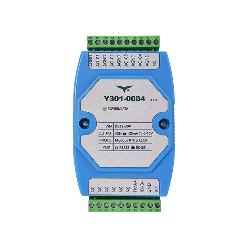
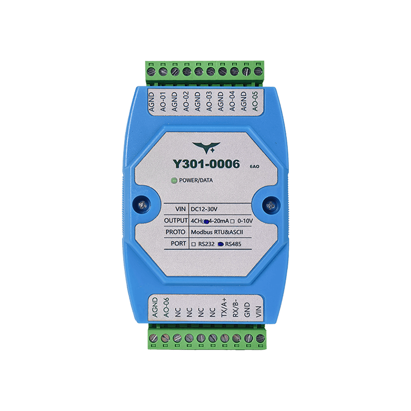
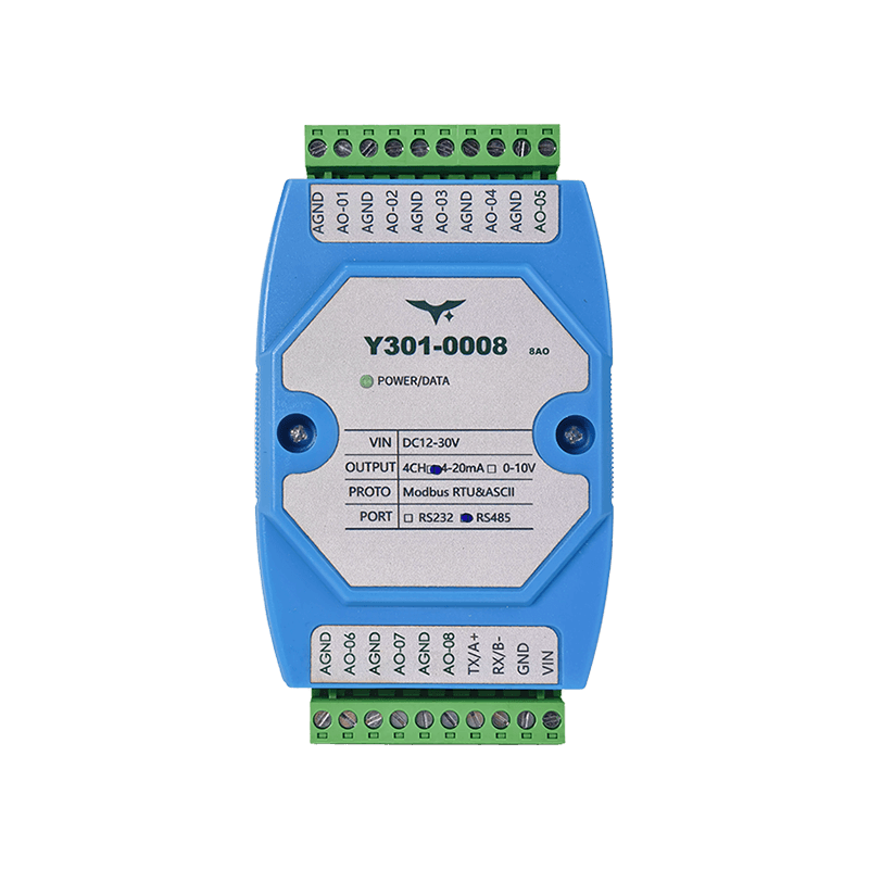
Appearance
Y301-0004/0006/0008 Analog Output Module Specification
| Y301-0004 | Y301-0006 | Y301-0008 |
|---|---|---|
 |  |  |
Manufacturer: Hunan YenGear Tech Co., Ltd.
Address: Room 21014, Building 1, Fudi Xingguang Tiandi, Yingxin Road, Yuhua District, Changsha, Hunan, China
Email: hi@yengear.com
Website: www.yengear.com
Contents
- Overview
- Ordering Information
- Key Features
- Technical Specifications
- Interfaces and Pinout
- Wiring Guidelines
- Communication and Configuration
- Diagnostics and FAQ
1. Overview
The Y301-0004/0006/0008 are analog output concentrators based on the DAM0800AO-YD platform. They provide deterministic Modbus RTU/ASCII control of 0-10 V and/or 4-20 mA channels for PLCs, SCADA systems, building automation, and lab platforms.
| Model | Analog Output | Interface Options | Typical Role |
|---|---|---|---|
| Y301-0004 | 4 AO | RS485 / RS232 | Small HVAC and OEM retrofits |
| Y301-0006 | 6 AO | RS485 / RS232 | Mid-size process skids |
| Y301-0008 | 8 AO | RS485 / RS232 | High-density analog drive |
Product Highlights
- 14-bit DAC with
0.001 V / 0.001 mAresolution - Configurable
0-10 Vand4-20 mAoutputs, with jumper-selectable combo versions - Opto-isolated RS485 plus optional RS232
- Plug-and-play Modbus integration with address retention and power-loss memory
2. Ordering Information
2.1 Model Naming
Y301-000X-IF-SIGNAL
- 000X -
0004(4 AO),0006(6 AO),0008(8 AO) - IF -
RS485orRS232 - SIGNAL - voltage only, current only, or combo (
0-10 V/4-20 mAswitched by jumper)
2.2 SKU Matrix
| SKU | Interface | Output Mode | Description |
|---|---|---|---|
| Y301-0004-RS485-V | RS485 | 0-10 V | 4-channel voltage driver |
| Y301-0004-RS232-I | RS232 | 4-20 mA | 4-channel current driver |
| Y301-0004-RS485-C | RS485 | 0-10 V / 4-20 mA (combo) | Jumper-selectable mixed-use version |
| Y301-0006-RS485-C | RS485 | Combo | 6-channel AO |
| Y301-0006-RS232-C | RS232 | Combo | 6-channel AO |
| Y301-0008-RS485-C | RS485 | Combo | 8-channel AO |
| Y301-0008-RS232-C | RS232 | Combo | 8-channel AO |
Combo SKUs use internal jumpers to switch each channel between voltage and current output.
2.3 Standard Package
Module, quick reference guide, and warranty card. Optional accessories include a DIN-rail 24 V power supply, USB-to-RS485 converter, and shielded harness kit.
3. Key Features
- High-resolution DAC - Native 14-bit engine with
0.001 V / 0.001 mAoutput steps - Robust output stage - Directly drives
0-10 Vvoltage loops or4-20 mAcurrent loops with fault protection - Flexible protocol support - Modbus RTU, ASCII, and Modbus TCP through a host gateway; address range
1-255 - Wide input and isolation -
12-30 VDCsupply, opto-isolated RS485, and surge-tolerant design - Power-loss memory - Optional retention restores the last analog output after reboot
- JYDAM toolchain - GUI tool for multi-channel writes, batch setpoints, Excel logging, and auto baud-rate discovery
4. Technical Specifications
4.1 Electrical and Environmental
| Parameter | Specification |
|---|---|
| Supply voltage | 12-30 VDC |
| Typical power consumption | 11 mA @ 24 V (~0.26 W) |
| Isolation | Opto-isolated RS485 |
| Operating temperature | -40 to +85 C |
| Humidity | 0-95% RH, non-condensing |
| Dimensions | 100 x 70 x 35 mm |
4.2 Analog Output Specifications
| Parameter | Specification |
|---|---|
| Channel count | 4, 6, or 8 depending on model |
| Output type | 0-10 V or 4-20 mA, configurable per channel |
| Resolution | 14-bit (16384 steps) |
| Accuracy | +/-0.1% FS |
| Linearity | +/-0.1% FS |
| Settling time | <10 ms |
| Output impedance | Voltage mode: <10 ohm; current mode: >10 Mohm |
| Load capability | Voltage mode: >2 kohm; current mode: <600 ohm |
4.3 Communication Specifications
| Parameter | Specification |
|---|---|
| Interface | Opto-isolated RS485, optional RS232 |
| Protocol | Modbus RTU, Modbus ASCII, Modbus TCP (via gateway) |
| Baud rate | 600-115200 bps (auto-detect) |
| Address range | 1-255 |
| Isolation voltage | 1500 V RMS |
5. Interfaces and Pinout
5.1 Terminal Layout
| Terminal | Description |
|---|---|
| Power | V+, V- (12-30 VDC) |
| RS485 | A, B, GND (opto-isolated) |
| RS232 | TX, RX, GND (optional) |
| AO output | AO1+, AO1-, AO2+, AO2-, etc. depending on model |
| Configuration | Jumpers for voltage/current mode selection |
5.2 LED Indicators
| LED | Status | Description |
|---|---|---|
| Power | Solid green | Power is normal |
| Communication | Flashing green | Bus activity detected |
| Fault | Solid red | Fault detected |
6. Wiring Guidelines
6.1 Power Connection
- Use 18-22 AWG wiring for the 12-30 VDC supply
- Add a 1 A fuse for overcurrent protection
- Verify correct polarity before power-on
6.2 Output Connection
Voltage mode (0-10 V):
- Connect the load positive terminal to
AO+and the negative terminal toAO- - Load impedance should be greater than
2 kohmfor best accuracy
Current mode (4-20 mA):
- Wire the load in series with the output loop
- Total loop impedance should be less than
600 ohm - Suitable for 2-wire or 4-wire instruments
6.3 Communication Connection
RS485:
- Use shielded twisted pair
- Add 120 ohm termination resistors at both ends of the bus
- Connect
AtoA,BtoB, andGNDtoGNDacross all devices
RS232:
- Connect directly to a DTE device
- Maximum cable length is 15 m
7. Communication and Configuration
7.1 Modbus Register Map
| Address | Function | Description |
|---|---|---|
| 40001 | AO1 output value | 0-10000 corresponds to 0-10 V or 0-20 mA |
| 40002 | AO2 output value | 0-10000 corresponds to 0-10 V or 0-20 mA |
| ... | ... | ... |
| 40008 | AO8 output value | 0-10000 corresponds to 0-10 V or 0-20 mA |
7.2 Configuration Parameters
| Parameter | Address | Description |
|---|---|---|
| Baud rate | 40301 | 0=9600, 1=19200, 2=38400, 3=115200 |
| Address | 40302 | Modbus slave address (1-255) |
| Output mode | 40303 | Bitwise voltage/current mode setting for each channel |
8. Diagnostics and FAQ
8.1 Troubleshooting
| Symptom | Possible Cause | Solution |
|---|---|---|
| No output response | Power fault | Check supply wiring and input voltage |
| Communication failure | Baud-rate mismatch | Use auto baud-rate detection |
| Poor output accuracy | Incorrect load impedance | Verify load impedance requirements |
8.2 FAQ
Q: How do I change the output mode? A: Use the internal jumper or register 40303 to configure voltage/current mode for each channel.
Q: Which communication protocols are supported? A: Modbus RTU, Modbus ASCII, and Modbus TCP through a gateway are supported.
Q: How does power-loss memory work? A: When enabled, the module restores the last output value after reboot.
- Manufacturer: Hunan YenGear Tech Co., Ltd.
- Address: Room 21014, Building 1, Fudi Xingguang Tiandi, Yingxin Road, Yuhua District, Changsha, Hunan, China
- Email: hi@yengear.com
- Website: www.yengear.com