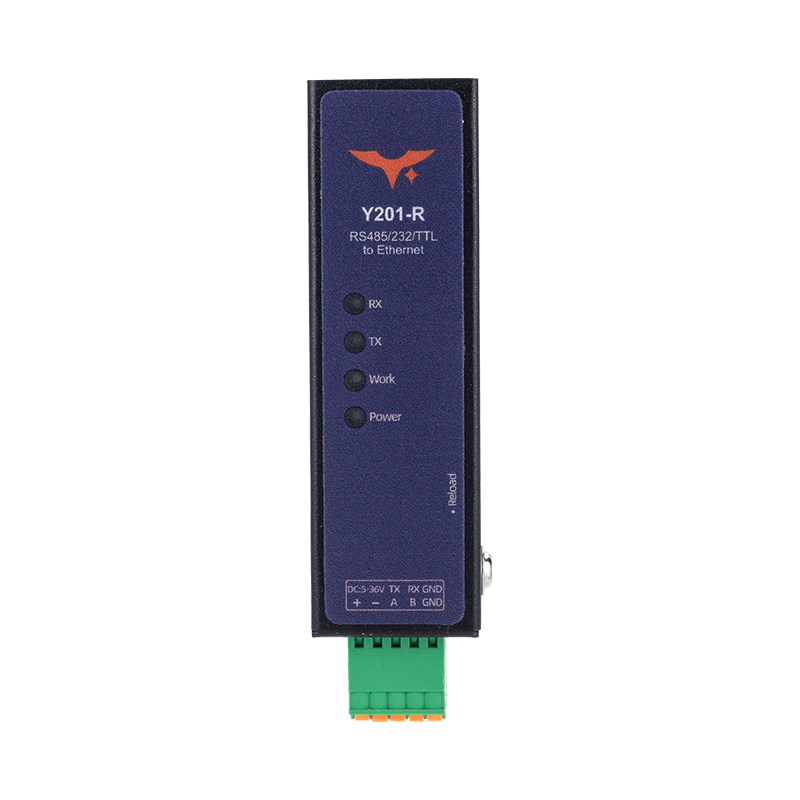
Appearance
Y201-R Technical Manual
Contents
- Overview
- Default Access Information
- Quick Configuration Flow
- Web UI Overview
- Socket and Protocol Configuration
- Modbus Gateway
- Registration Packets and Heartbeats
- Typical Debug Examples
- Troubleshooting
1. Overview
Y201-R is a data terminal for bidirectional transfer between serial and Ethernet networks. It supports RS485, RS232, or TTL serial access together with RJ45 Ethernet. Parameters can be configured through the Web UI, and communication links can be established through Socket A and B using TCP, UDP, HTTP, or MQTT.
| Item | Description |
|---|---|
| Core Capability | Bidirectional transfer between serial data and Ethernet data |
| Serial Interface | RS485 / RS232 / TTL, depending on SKU |
| Network Protocols | TCP / UDP / HTTP client / MQTT client |
| Configuration Entry | Browser-based Web UI |
| Extended Function | Modbus RTU to Modbus TCP gateway |
2. Default Access Information
| Item | Default |
|---|---|
| Management Address | 192.168.10.8 |
| Username | admin |
| Password | admin |
Before access, set the PC NIC to the same subnet as the device and make sure the subnet mask and default gateway match.
3. Quick Configuration Flow
Recommended sequence:
- Power on the device and connect the PC and the device with an Ethernet cable.
- Change the PC NIC to the same subnet as the device.
- Open
192.168.10.8in a browser and log in. - Configure network parameters, static IP or DHCP.
- Configure serial parameters to match the field device.
- Configure the required Socket protocol, TCP, UDP, HTTP, or MQTT.
- Enable the Modbus gateway, registration packet, and heartbeat as needed.
- Save the parameters and reboot the device.
- Verify communication with a host-side tool or cloud platform.
4. Web UI Overview
The Y201-R Web UI mainly includes the following pages:
- Status: Shows current runtime status and connection status
- System: Configures device network settings, system parameters, and reboot operations
- Port: Configures serial parameters, Socket parameters, Modbus gateway, registration packet, and heartbeat
Engineering recommendations:
- Save parameters immediately after changing critical settings.
- Reboot after changing network or protocol settings.
- During initial debugging, start with TCP or UDP and switch to HTTP or MQTT after the link is verified.
5. Socket and Protocol Configuration
5.1 Socket Capability
| Channel | Supported Protocols |
|---|---|
| Socket A | TCP server / TCP client / UDP server / UDP client / HTTP client / MQTT client |
| Socket B | TCP client / UDP server / UDP client |
5.2 TCP Server
- The device listens on a local port and waits for TCP clients.
- Each TCP server can support up to
8concurrent clients. - Serial data can be forwarded to all online clients.
5.3 TCP Client
- The device actively connects to the target server address and port.
- If the connection fails, it reconnects automatically with about a
1 sinterval. - This mode is suitable when the cloud platform or center acts as the server.
5.4 UDP Server
- Binds a local port and receives data from multiple clients.
- The default send target is the most recently communicating client.
- This mode is suitable for local debugging and lightweight data exchange.
5.5 UDP Client
- The target IP and port are fixed.
- A fixed local port is recommended so that return packets from the peer remain stable.
5.6 HTTP Client
Supports HTTP 1.0 / 1.1 and GET / POST / AUTO:
- GET: Serial data triggers a GET request as URL content
- POST: Serial data is sent as the request body to a preset URL
- AUTO: Request method and parameters are selected flexibly through the packet header mechanism
5.7 MQTT Client
- After the connection is established, the device can subscribe to a preset topic and publish data to a preset topic automatically.
- Supports
QoS0 / QoS1 / QoS2. - Supports both standard MQTT and Alibaba Cloud MQTT format.
QoS selection suggestions:
QoS0: Lowest latency, packet loss allowedQoS1: Balanced reliability and latencyQoS2: Highest reliability with the highest overhead
6. Modbus Gateway
6.1 Function Description
The Modbus gateway is disabled by default:
- Disabled: Transparent transfer between serial port and Ethernet
- Enabled: Performs Modbus RTU to Modbus TCP protocol conversion
6.2 Usage Recommendations
- Enable it when the host uses Modbus TCP and the field device uses Modbus RTU.
- Leave it disabled if only raw serial transparent transmission is required.
- If uncertain, validate both modes during debugging.
7. Registration Packets and Heartbeats
7.1 Registration Packet
The registration packet is used to report device identity to the server proactively when communication is established.
| Mode | Description |
|---|---|
FIRST | Sent once at first transmission, for TCP client after each successful connection and for UDP client after the network comes up |
EVERY | Prepends the registration header to every data transmission |
ALL | FIRST + EVERY |
7.2 Heartbeat Packet
Heartbeats are used for keepalive and link monitoring.
- Network heartbeat supports TCP and UDP client modes
- Serial heartbeat is independent of network mode
- Heartbeats pause while the device is in AT command state
8. Typical Debug Examples
8.1 TCP Server Debug, Device as Server
- Set the target Socket on the Port page to
TCPServer. - Configure the local listening port, for example
8010. - Save and reboot.
- Use a host-side network tool in TCP client mode and connect to the device IP and port.
- Send serial data and verify that it is forwarded to the host.
8.2 TCP Client Debug, Device as Client
- Set the target Socket on the Port page to
TCPClient. - Enter the host or server address and port.
- Save and reboot, then observe the device establishing the connection automatically.
- Check the connection on the server and test bidirectional data transfer.
8.3 UDP Server and UDP Client Debug
- UDP Server: Use a host-side UDP client to send data to the local port on the device
- UDP Client: The device sends data to a fixed target IP and port, while the host runs a UDP server to receive it
8.4 HTTP and MQTT Debug Suggestions
- First verify the serial path with TCP or UDP.
- Then configure HTTP or MQTT server parameters.
- For MQTT, start with
QoS0for quick connectivity, then move toQoS1orQoS2based on reliability requirements.
9. Troubleshooting
| Symptom | Possible Cause | Recommended Action |
|---|---|---|
| Web UI cannot be opened | The PC and device are not on the same subnet | Check NIC IP settings and verify access to 192.168.10.8 |
| Login fails | Username or password is incorrect | Use default admin/admin or confirm whether the credentials were changed |
| Serial data exists but no Ethernet data | The Socket is not connected | Check Socket mode, target address, port, and connection state |
| TCP client cannot connect | Server address or port is wrong, or blocked by firewall | Verify address and port, and allow the required firewall rules |
| UDP packets cannot be returned | Local port is not fixed or the target settings are wrong | Fix the local port and verify the peer IP and port |
| Modbus communication fails | Incorrect gateway mode selection | Switch the Modbus gateway according to the host protocol |
| No data on cloud platform | HTTP or MQTT settings are wrong | Check server address, credentials, topic, and QoS |
| Parameters do not take effect after reboot | Parameters were not saved or the device was not rebooted | Save the configuration and reboot the device before verifying |
- Manufacturer: Hunan YenGear Tech Co., Ltd.
- Address: Room 21014, Building 1, Fudi Xingguang Tiandi, Yingxin Road, Yuhua District, Changsha, Hunan, China
- Email: hi@yengear.com
- Website: www.yengear.com