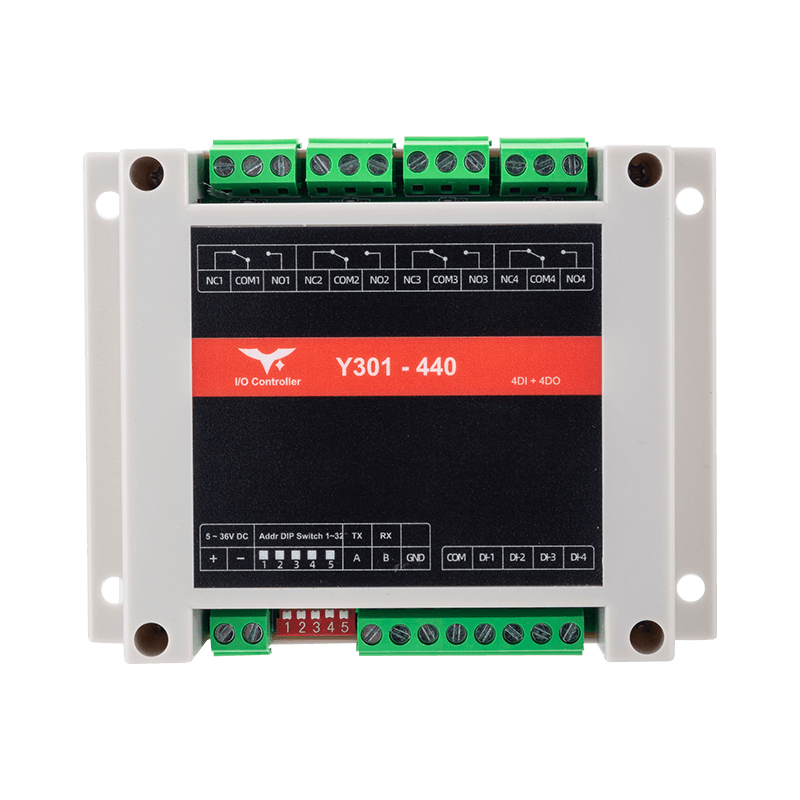
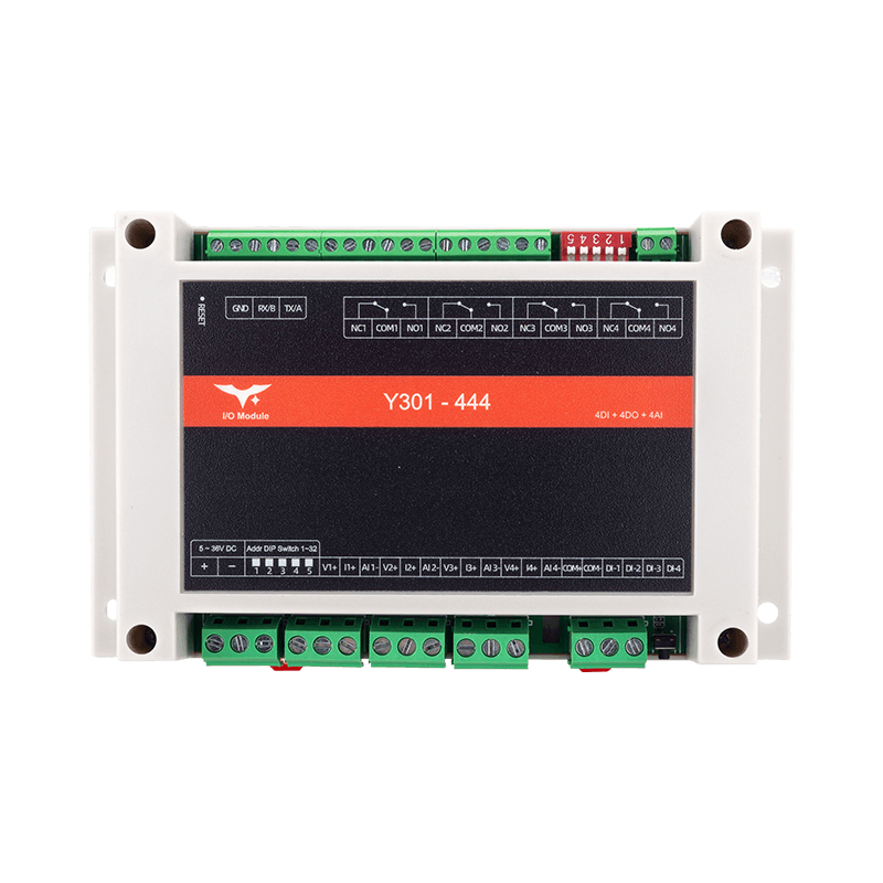
Appearance
Y301-440/444 I/O Module Specification
| Y301-440 | Y301-444 |
|---|---|
 |  |
Contents
- Overview
- Ordering Information
- Key Features
- Technical Specifications
- Interfaces and Pinout
- Mechanical and Environmental
- Automation Rules
1. Overview
The Y301-440/444 series provides Modbus RTU serial I/O expansion in two enclosure sizes.
| Model | DI | DO | AI | Typical Role |
|---|---|---|---|---|
| Y301-440 | 4 | 4 (SPDT) | - | Multi-zone digital automation |
| Y301-444 | 4 | 4 (SPDT) | 4 (0-10 V / 0-5 V / 4-20 mA) | Process control with analog sensing |
Product Highlights
- Shared Modbus RTU firmware with RS485, RS232, and TTL interface options
- DIN-rail or screw mounting with front-panel status LEDs for power, DI, and DO
- Y301-444 adds four analog inputs in a larger 145 x 90 x 40 mm enclosure
- Y301-440 keeps a compact 115 x 90 x 40 mm footprint for digital-only control
2. Ordering Information
2.1 Model Naming
Y301-XYZ
- XYZ: function combination (
440 = 4DI + 4DO + 0AI,444 = 4DI + 4DO + 4AI)
2.2 Interface Options
All models are available with the following serial interfaces:
| Interface | Description |
|---|---|
| RS485 | Standard version for Modbus RTU multi-drop networks |
| RS232 | Optional version for point-to-point communication |
| TTL | Optional on selected models for direct MCU integration |
2.3 SKU Matrix
| SKU | Description |
|---|---|
| Y301-440 | 4 DI + 4 DO, standard digital I/O node |
| Y301-444 | 4 DI + 4 DO + 4 AI, full-featured I/O node |
2.4 Package Contents
Module, digital quick reference guide, and warranty card. Optional accessories include a DIN clip, USB-to-RS485 converter, 12/24 VDC power supply, and shielded RS485 wiring kit.
3. Key Features
- High-power relays - Four SPDT contacts per model, rated at 277 VAC / 10 A or 28 VDC / 10 A
- Opto-isolated DI - Four dry/wet contact inputs with pulse counting and configurable debounce
- Analog input on Y301-444 - Four channels, each configurable for 0-10 V, 0-5 V, or 4-20 mA, with 16-bit resolution and +/-1% FS accuracy
- Embedded automation - Up to 8 local rules, including follow, pulse, delay, schedule, logic, and AI threshold modes
- Retention and addressing - DO retention plus 5-bit DIP offset stacked on the software Modbus address
- Industrial design - 5-36 VDC input, -40 to +85 C environment, hardware watchdog, Reload button, and surge-protected communication ports
4. Technical Specifications
4.1 Electrical and Environmental
| Parameter | Specification |
|---|---|
| Supply voltage | 5-36 VDC |
| Typical current | 200 mA @ 12 V (all DO off) |
| Maximum current | 280 mA @ 12 V (four relays on + AI sampling) |
| Operating temperature | -40 to +85 C |
| Humidity | 5-95% RH, non-condensing |
| Altitude | <= 2000 m |
4.2 Digital Input (4 channels)
| Item | Specification |
|---|---|
| Type | Dry/wet contact, opto-isolated |
| Voltage range | 5-36 V (wet contact mode) |
| Input current | <5 mA per channel |
| Sampling rate | 100 Hz |
| Pulse counter | 32-bit, selectable rising/falling edge |
| Debounce | 5-255 ms (default 50 ms) |
4.3 Digital Output (4 x SPDT relays)
| Item | Specification |
|---|---|
| Contact rating | 277 VAC 10 A / 28 VDC 10 A |
| Minimum load | 10 VAC 10 mA |
| Switching time | <10 ms operate / <5 ms release |
| Electrical life | 100k cycles at rated load |
| Output retention | None / soft reboot / full retention |
4.4 Analog Input (Y301-444, 4 channels)
| Item | Specification |
|---|---|
| Input type | 0-10 V, 0-5 V, or 4-20 mA, configurable per channel |
| Resolution | 16-bit |
| Accuracy | +/-1% FS |
| Sampling rate | 10 Hz |
| Input impedance | Voltage mode: >100 kohm; current mode: 250 ohm |
| Overvoltage protection | +/-30 V |
4.5 Communication
| Item | Specification |
|---|---|
| Interface | RS485 (2-wire), optional RS232 or TTL |
| Protocol | Modbus RTU slave |
| Baud rate | 600-230400 bps (default 9600) |
| Slave address | 1-255 (software) + DIP offset 0-31 |
5. Interfaces and Pinout
5.1 Terminal Overview
| Group | Description |
|---|---|
| Power | V+, V- screw terminals + DC 5.5 x 2.1 mm jack |
| DIP switch | SW1-SW5 (binary address offset) |
| Reload | Hold 3-15 s to restore factory defaults |
| DI | COM+, COM-, DI1-DI4 |
| DO | NCn / COMn / NOn for channels 1-4 |
| AI (444 only) | AI1+, AI1-, AI2+, AI2-, AI3+, AI3-, AI4+, AI4- |
| Communication | A/B/GND (RS485) or TX/RX/GND (RS232/TTL) |
5.2 Wiring Guidelines
- Use 20-16 AWG power wiring with a 2 A upstream fuse.
- For dry-contact DI, bridge
COM+to the targetDIthrough the external contact. - For wet-contact DI, connect the external 5-36 V reference to
COM-. - For relay outputs driving inductive loads, add an RC snubber for AC loads or a flyback diode for DC loads.
- For Y301-444 analog input wiring, connect the source directly in voltage mode and use the current loop terminals in current mode.
- For RS485, use shielded twisted pair, terminate both ends with 120 ohm resistors, and keep a common reference ground.
6. Mechanical and Environmental
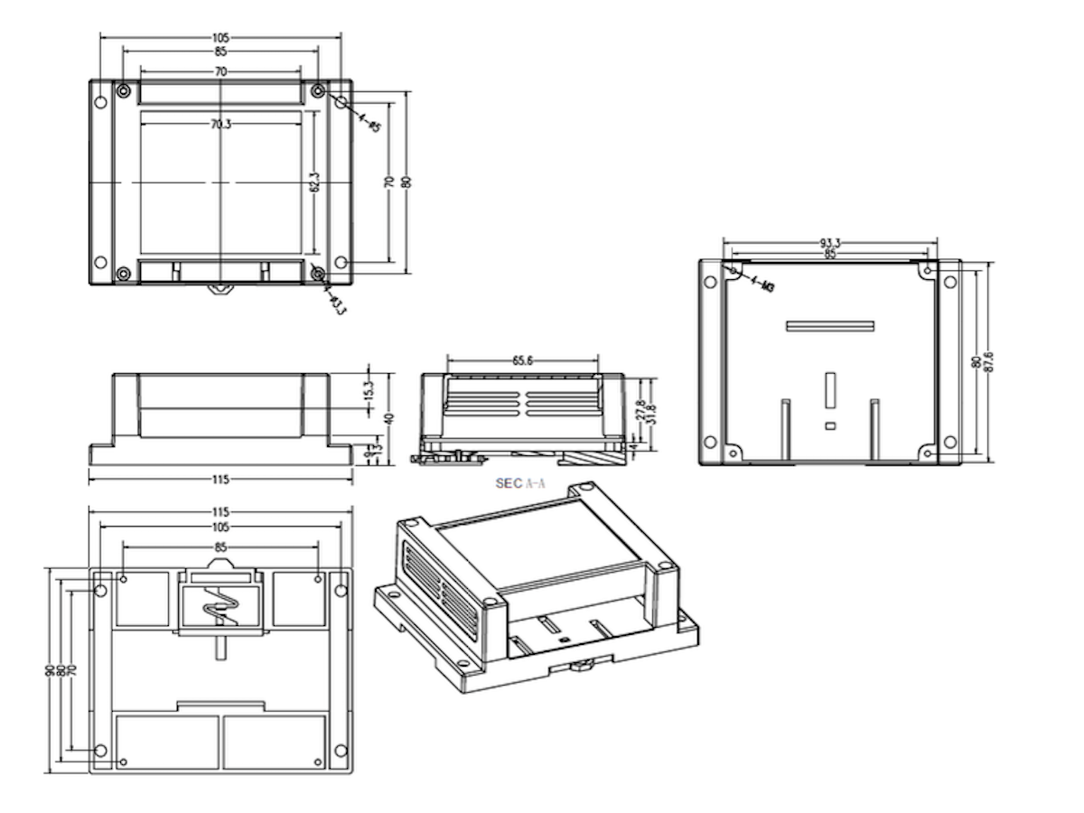
| Item | Y301-440 | Y301-444 |
|---|---|---|
| Dimensions | 115 x 90 x 40 mm | 145 x 90 x 40 mm |
| Mounting | 35 mm DIN clip or screw slots | 35 mm DIN clip or screw slots |
| Protection | IP20 | IP20 |
| Housing | UL94 V-0 flame-retardant plastic | UL94 V-0 flame-retardant plastic |
Keep at least 15 mm clearance above and below, 10 mm on each side, and 40 mm in front for wiring and airflow.
7. Automation Rules
| Mode | Description |
|---|---|
| DI follow | DO mirrors the DI state |
| Pulse output | Configurable ON/OFF pulse width |
| Delay control | Programmable ON/OFF delay |
| Cyclic toggle | Periodic ON/OFF cycling |
| Timer/schedule | Time-based activation |
| AI threshold (444) | Triggered by analog input threshold |
| Logic mode | AND/OR logic combination |
| Watchdog mode | Automatically resets the DO when the timeout condition occurs |
- Up to 8 rules total, with up to 2 rules per DO channel
- Rules run locally without host polling
- When enabled, output retention stores the last automation state
- Manufacturer: Hunan YenGear Tech Co., Ltd.
- Address: Room 21014, Building 1, Fudi Xingguang Tiandi, Yingxin Road, Yuhua District, Changsha, Hunan, China
- Email: hi@yengear.com
- Website: www.yengear.com