Appearance
Y301-110/200/020 I/O Module Specification
| Y301-110 | Y301-200 | Y301-020 |
|---|---|---|
 |  |  |
Contents
- Overview
- Ordering Information
- Key Features
- Technical Specifications
- Interfaces and Pinout
- Mechanical and Environmental
- Automation Rules
1. Overview
The Y301-110/200/020 series includes ultra-compact serial I/O modules for industrial automation, remote monitoring, and IoT edge deployments. Each model combines opto-isolated digital inputs and relay outputs, with Modbus RTU over RS485 by default and optional RS232/TTL variants for easy integration with PLCs, SCADA systems, and cloud-connected data loggers.
| Model | Digital Input (DI) | Digital Output (DO) | Typical Use Case |
|---|---|---|---|
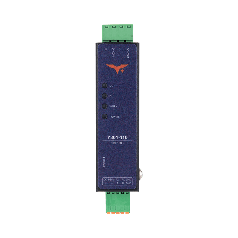
| Y301-110 | 1 | 1 | Local alarm input and actuator control |
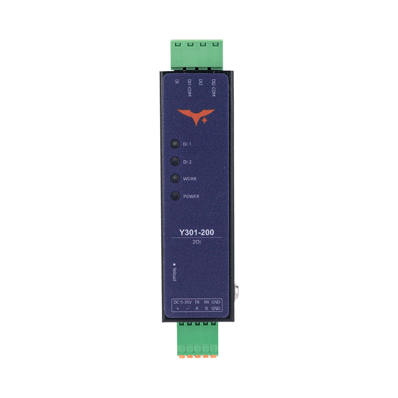
| Y301-200 | 2 | 0 | Dual-channel status monitoring |
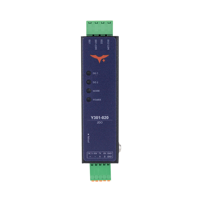
| Y301-020 | 0 | 2 | Dual relay control for pumps or valves |
Product Highlights
- Compact DIN-rail or panel-mount form factor for dense control cabinets
- Industrial 5-36 VDC input with reverse-polarity protection
- Well suited for edge gateways, OEM equipment, and smart building nodes that need modular I/O expansion
2. Ordering Information
2.1 Model Naming
Y301-XYZ
- XYZ: function combination (
110 = 1DI + 1DO + 0AI,200 = 2DI + 0DO + 0AI,020 = 0DI + 2DO + 0AI)
2.2 Interface Options
All models are available with the following serial interfaces:
| Interface | Description |
|---|---|
| RS485 | Standard version for Modbus RTU multi-drop networks |
| RS232 | Optional version for point-to-point communication |
| TTL | Optional on selected models for direct MCU integration |
2.3 Ordering Table
| SKU | Description |
|---|---|
| Y301-110 | 1 DI + 1 DO, Modbus RTU |
| Y301-200 | 2 DI, input-only module |
| Y301-020 | 2 DO, output-only module |
2.4 Package Contents
Module, digital quick reference guide, and warranty card. Optional accessories include a DIN clip, USB-to-RS485 converter, 12/24 VDC power supply, and shielded RS485 wiring kit.
3. Key Features
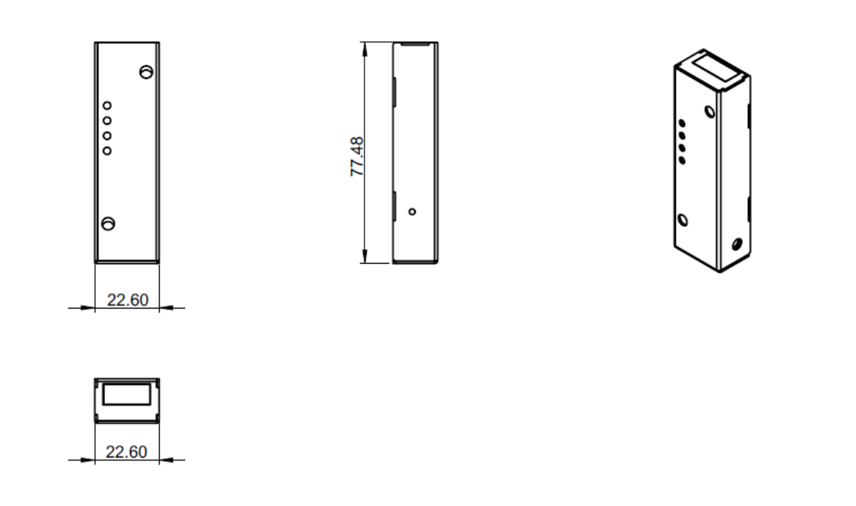
- Ultra-compact design - 77 mm class enclosure for space-constrained installations
- Flexible configuration - Three model variants cover common digital I/O requirements
- Modbus RTU ready - RS485/RS232/TTL interface options simplify system integration
- Industrial reliability - 5-36 VDC input and -40 to +85 C operating range
- Opto-isolated inputs - Supports both dry contact and wet contact signals
- High-power relay outputs - Rated up to 277 VAC / 10 A or 28 VDC / 10 A
- Built-in automation - Supports local logic rules and output retention
- DIP addressing - 5-bit DIP switch supports multi-device deployments
4. Technical Specifications
4.1 Electrical and Environmental
| Parameter | Specification |
|---|---|
| Supply voltage | 5-36 VDC |
| Typical current | 80 mA @ 12 V (all DO off) |
| Maximum current | 120 mA @ 12 V (all DO on) |
| Operating temperature | -40 to +85 C |
| Humidity | 5-95% RH, non-condensing |
| Altitude | <= 2000 m |
4.2 Digital Input
| Item | Specification |
|---|---|
| Channel count | 1 (Y301-110) or 2 (Y301-200) |
| Type | Dry/wet contact, opto-isolated |
| Voltage range | 5-36 V (wet contact mode) |
| Input current | <5 mA per channel |
| Sampling rate | 100 Hz |
| Pulse counter | 32-bit, selectable rising/falling edge |
| Debounce | 5-255 ms (default 50 ms) |
4.3 Digital Output
| Item | Specification |
|---|---|
| Channel count | 1 (Y301-110) or 2 (Y301-020) |
| Type | SPDT relay |
| Contact rating | 277 VAC 10 A / 28 VDC 10 A |
| Minimum load | 10 VAC 10 mA |
| Switching time | <10 ms operate / <5 ms release |
| Electrical life | 100k cycles at rated load |
| Output retention | None / soft reboot / full retention |
4.4 Communication
| Item | Specification |
|---|---|
| Interface | RS485 (2-wire), optional RS232 or TTL |
| Protocol | Modbus RTU slave |
| Baud rate | 600-230400 bps (default 9600) |
| Slave address | 1-255 (software) + DIP offset 0-31 |
5. Interfaces and Pinout
5.1 Terminal Overview
| Group | Y301-110 | Y301-200 | Y301-020 |
|---|---|---|---|
| Power | V+, V- screw terminals + DC 5.5 x 2.1 mm jack | V+, V- screw terminals + DC 5.5 x 2.1 mm jack | V+, V- screw terminals + DC 5.5 x 2.1 mm jack |
| DIP switch | SW1-SW5 (binary address offset) | SW1-SW5 (binary address offset) | SW1-SW5 (binary address offset) |
| Reload | Hold 3-15 s to restore factory defaults | Hold 3-15 s to restore factory defaults | Hold 3-15 s to restore factory defaults |
| DI | COM+, COM-, DI1 | COM+, COM-, DI1-DI2 | None |
| DO | NC1 / COM1 / NO1 | None | NC1/NC2 / COM1/COM2 / NO1/NO2 |
| Communication | A/B/GND (RS485) or TX/RX/GND (RS232/TTL) | A/B/GND (RS485) or TX/RX/GND (RS232/TTL) | A/B/GND (RS485) or TX/RX/GND (RS232/TTL) |
5.2 Wiring Guidelines
- Use 20-16 AWG power wiring with a 1 A upstream fuse.
- For dry-contact DI, bridge
COM+to the targetDIthrough the external contact. - For wet-contact DI, connect the external 5-36 V reference to
COM-. - For relay outputs driving inductive loads, add an RC snubber for AC loads or a flyback diode for DC loads.
- For RS485, use shielded twisted pair, terminate both ends with 120 ohm resistors, and keep a common reference ground.
6. Mechanical and Environmental
| Item | Value |
|---|---|
| Dimensions | 77 x 54 x 32 mm |
| Mounting | 35 mm DIN clip or screw slots |
| Protection | IP20 |
| Housing | UL94 V-0 flame-retardant plastic |
Keep at least 15 mm clearance above and below, 10 mm on each side, and 40 mm in front for wiring and airflow.
7. Automation Rules
| Mode | Description |
|---|---|
| DI follow | DO mirrors the DI state |
| Pulse output | Configurable ON/OFF pulse width |
| Delay control | Programmable ON/OFF delay |
| Cyclic toggle | Periodic ON/OFF cycling |
| Timer/schedule | Time-based activation |
| Logic mode | AND/OR logic combination |
| Watchdog mode | Automatically resets the DO when the DI timeout condition occurs |
- Up to 2 rules total, with 1 rule per DO channel
- Rules run locally without host polling
- When enabled, output retention stores the last automation state
- Manufacturer: Hunan YenGear Tech Co., Ltd.
- Address: Room 21014, Building 1, Fudi Xingguang Tiandi, Yingxin Road, Yuhua District, Changsha, Hunan, China
- Email: hi@yengear.com
- Website: www.yengear.com