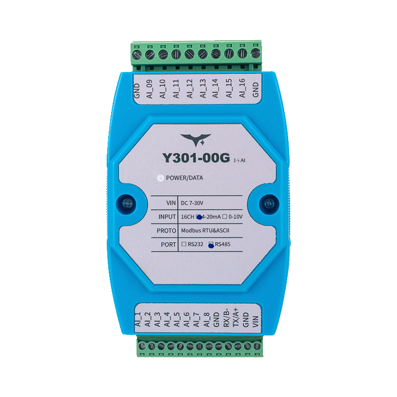
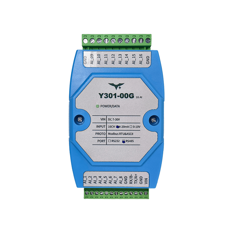
Appearance
Y301-006/008/00G Analog Input Module Specification
| Y301-006 | Y301-008 | Y301-00G |
|---|---|---|
 |  |  |
Manufacturer: Hunan YenGear Tech Co., Ltd.
Address: Room 21014, Building 1, Fudi Xingguang Tiandi, Yingxin Road, Yuhua District, Changsha, Hunan, China
Email: hi@yengear.com
Website: www.yengear.com
Contents
- Overview
- Ordering Information
- Key Features
- Technical Specifications
- Interfaces and Pinout
- Wiring Guidelines
- Mechanical and Environmental
- Communication and Configuration
- Diagnostics and FAQ
1. Overview
The Y301-006/008/00G series is a family of multi-channel analog input concentrators based on the DAM1600AI-YD hardware platform. The modules acquire 4-20 mA or 0-10 V signals over a Modbus RTU/ASCII link and transfer normalized values to PLCs, SCADA systems, or edge controllers.
| Model | Analog Input | Interface Options | Typical Application |
|---|---|---|---|
| Y301-006 | 6 channels | RS485 / RS232 | Compact HVAC and OEM skids |
| Y301-008 | 8 channels | RS485 / RS232 | Building automation and lab systems |
| Y301-00G | 16 channels | RS485 / RS232 | High-density telemetry panels |
Product Highlights
- 12-bit ADC with linear scaling (
actual value = register x 0.001) - Wide 7-30 VDC supply range with a single status LED
- 35 mm DIN-rail enclosure, 100 x 70 x 35 mm
- Broadcast-friendly commissioning with default address 0 and broadcast address 254
2. Ordering Information
2.1 Model Naming
Y301-00X-IF
- 00X -
006(6 AI),008(8 AI),00G(16 AI) - IF -
RS485(multi-drop) orRS232(point-to-point)
2.2 SKU Matrix
| SKU | Interface | Description |
|---|---|---|
| Y301-006-RS485 | RS485 | 6-channel analog input concentrator |
| Y301-006-RS232 | RS232 | 6-channel point-to-point module |
| Y301-008-RS485 | RS485 | 8-channel analog input concentrator |
| Y301-008-RS232 | RS232 | 8-channel point-to-point module |
| Y301-00G-RS485 | RS485 | 16-channel analog input concentrator |
| Y301-00G-RS232 | RS232 | 16-channel point-to-point module |
2.3 Standard Package
Module, online quick reference card, and warranty card. Optional accessories include shielded twisted-pair cable, USB-to-RS485 converter, and a 12/24 V DIN-rail power supply.
3. Key Features
- Scalable AI platform - 6, 8, and 16 channel variants with per-channel LED indication
- Dual serial options - RS485 multi-drop (
A/B/GND) and RS232 (TX/RX/GND) share the same firmware base - Flexible signal support - Accepts 4-20 mA loops or 0-10 V inputs and supports 2-wire, 3-wire, and 4-wire sensors
- Modbus compatible - Function code
0x04for analog reads and0x03/0x06for address and baud-rate settings - Industrial build - -40 to +85 C operation, 5-95% RH, and reverse-polarity-tolerant 7-30 V input
- JYDAM utility - Free diagnostic tool for live trending, Excel export, offset/baud adjustment, and broadcast discovery
4. Technical Specifications
4.1 Electrical and Environmental
| Parameter | Specification |
|---|---|
| Supply voltage | 7-30 VDC |
| Typical power consumption | <1.5 W |
| Indicators | 1 x power LED, per-channel AI LED |
| Operating temperature | -40 to +85 C |
| Humidity | 5-95% RH, non-condensing |
| Dimensions | 100 x 70 x 35 mm |
| Mounting | 35 mm DIN rail |
| Weight | Approx. 60 g |
4.2 Analog Input Specifications
| Parameter | Specification |
|---|---|
| Channel count | 6, 8, or 16 depending on model |
| Input type | 4-20 mA or 0-10 V, configurable per channel |
| Resolution | 12-bit (4096 steps) |
| Accuracy | +/-0.5% FS |
| Linearity | +/-0.5% FS |
| Sampling rate | 10 Hz |
| Input impedance | Voltage mode: >100 kohm; current mode: 250 ohm |
| Overvoltage protection | +/-30 V |
4.3 Communication Specifications
| Parameter | Specification |
|---|---|
| Interface | RS485, RS232 |
| Protocol | Modbus RTU, Modbus ASCII |
| Baud rate | 600-115200 bps |
| Address range | 1-255 |
| Isolation | Non-isolated |
5. Interfaces and Pinout
5.1 Terminal Layout
| Terminal | Description |
|---|---|
| Power | V+, V- (7-30 VDC) |
| RS485 | A, B, GND |
| RS232 | TX, RX, GND |
| AI input | AI1+, AI1-, AI2+, AI2-, etc. depending on model |
5.2 LED Indicators
| LED | Status | Description |
|---|---|---|
| Power | Solid green | Power is normal |
| AI1-AI16 | Flashing green | Signal present on the corresponding channel |
6. Wiring Guidelines
6.1 Power Connection
- Use 18-22 AWG wiring for the 7-30 VDC supply
- Add a 500 mA fuse for overcurrent protection
- Verify correct polarity before power-on
6.2 Sensor Connection
Voltage mode (0-10 V):
- Connect the sensor positive lead to
AI+and the negative lead toAI- - Suitable for 3-wire voltage sensors
Current mode (4-20 mA):
- Wire the sensor in series with the
AI+andAI-current loop - Suitable for 2-wire or 4-wire current transmitters
6.3 Communication Connection
RS485:
- Use shielded twisted pair
- Add 120 ohm termination resistors at both ends of the bus
- Connect
AtoA,BtoB, andGNDtoGNDacross all devices
RS232:
- Connect directly to a DTE device
- Maximum cable length is 15 m
7. Mechanical and Environmental
| Item | Value |
|---|---|
| Dimensions | 100 x 70 x 35 mm |
| Mounting | 35 mm DIN rail |
| Protection | IP20 |
| Housing | ABS plastic |
| Weight | Approx. 60 g |
Keep at least 15 mm clearance above and below, and 10 mm on each side for wiring and airflow.
8. Communication and Configuration
8.1 Modbus Register Map
| Address | Function | Description |
|---|---|---|
| 40001 | AI1 input value | 0-10000 corresponds to 0-10 V or 4-20 mA |
| 40002 | AI2 input value | 0-10000 corresponds to 0-10 V or 4-20 mA |
| ... | ... | ... |
| 40016 | AI16 input value | 0-10000 corresponds to 0-10 V or 4-20 mA |
8.2 Configuration Parameters
| Parameter | Address | Description |
|---|---|---|
| Baud rate | 40301 | 0=9600, 1=19200, 2=38400, 3=115200 |
| Address | 40302 | Modbus slave address (1-255) |
9. Diagnostics and FAQ
9.1 Troubleshooting
| Symptom | Possible Cause | Solution |
|---|---|---|
| No channel reading | Sensor fault | Check sensor wiring and power |
| Communication failure | Baud-rate mismatch | Use broadcast address 254 for auto-detection |
| Unstable reading | Poor wiring | Check shielding and grounding |
9.2 FAQ
Q: How do I configure the input type for each channel? A: Use the internal jumper or configuration tool to set voltage or current mode per channel.
Q: Which communication protocols are supported? A: Modbus RTU and Modbus ASCII are supported.
Q: How can I discover devices on the bus? A: Send a query with broadcast address 254. The device will respond with its configured address.
- Manufacturer: Hunan YenGear Tech Co., Ltd.
- Address: Room 21014, Building 1, Fudi Xingguang Tiandi, Yingxin Road, Yuhua District, Changsha, Hunan, China
- Email: hi@yengear.com
- Website: www.yengear.com