Appearance
Y403-11-L Wireless I/O Sync System Manual
Refer to the detailed specification for electrical ratings, pinouts, and installation requirements: Y403-11-L Specification.
1. Overview
The Y403-11-L is a wireless linkage switch controller based on LoRa modulation technology with automatic relay transmission capability. In environments with severe obstructions, multiple nodes can be deployed to automatically search for optimal communication paths. Switch signals transmit wirelessly from one node to another with relay functionality, enabling signals to travel much farther.
2. Basic Setup
- Power all nodes with a stable DC supply per the datasheet.
- Pair factory-matched units; add new slaves following the pairing method in the specification.
- Wire dry-contact inputs to DI terminals; avoid applying active voltage signals.
- Connect relay outputs via NO/COM/NC to the controlled loads.
- Install antennas vertically and keep them away from large metal objects to maximize range.
3. Safety Notes
- Use certified power supplies and correct polarity.
- Avoid explosive, high-humidity, or dusty environments.
- Keep antennas within the specified operating band to ensure link reliability.
4. Pairing Method
Nodes are paired before leaving the factory and can communicate freely. If additional nodes are required, purchase a node Y403-11-L and pair it with any node in the existing system. After pairing, it can communicate within the system. The pairing process is as follows:
Electrical wiring: connect 2 power lines and 3 communication lines.
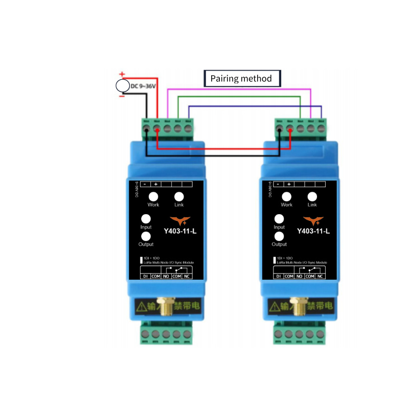
Power supply: provide (9\sim 36V) power. After normal power-on, the working indicators of both devices remain steadily lit.
Automatic configuration: within approximately 30 seconds, the connection indicators of both devices remain steadily lit, indicating pairing is complete. If the connection indicators do not remain steadily lit after 30 seconds, power off and check if the wiring is properly connected, then power on again to pair.
After pairing is complete, disconnect the communication lines. The device can then join the system for normal communication.
5. Wiring Instructions
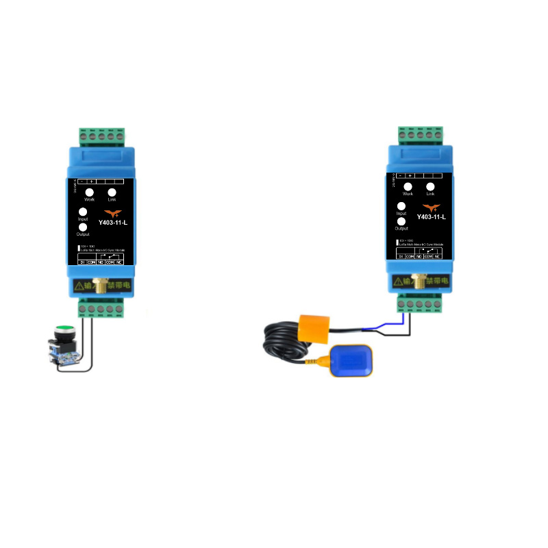
5.1 Input Connection
General mechanical switches (such as self-locking switches, float switches, intermediate relay outputs) that carry no voltage can be directly connected to the input of the device.
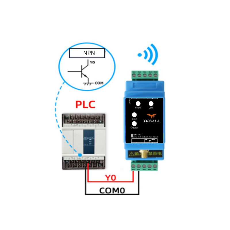
Connecting to NPN Signal
An NPN signal can also be connected to the input of the device. The emitter of the NPN signal is connected to the common terminal, and the collector is connected to the input terminal. These two NPN signals must not be connected to any other power source. Refer to the diagram below for wiring:
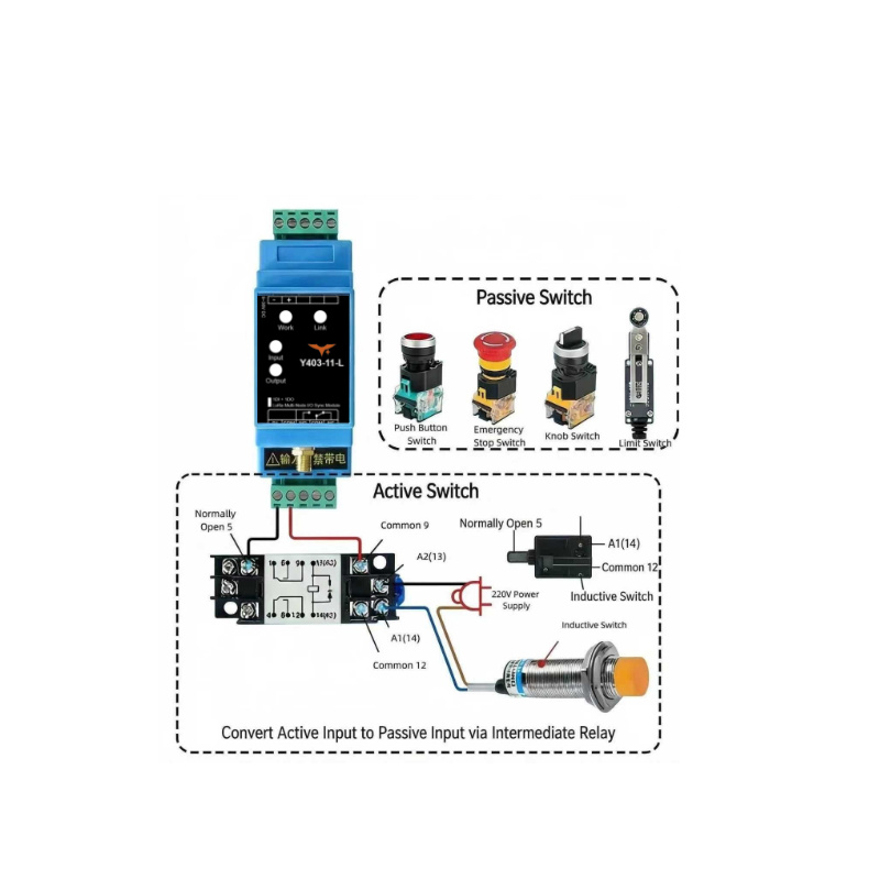
Connecting to Active Signal
An intermediate relay or similar method must be used to convert the active signal into a passive signal before it can be connected to the input of the device.
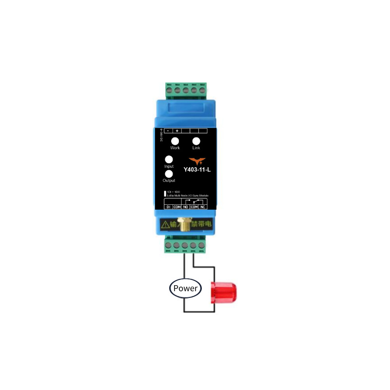
5.2 Output Connection
Connecting to Load
For devices with control power within 1kW (pure resistive load), they can be directly connected in series to the device.
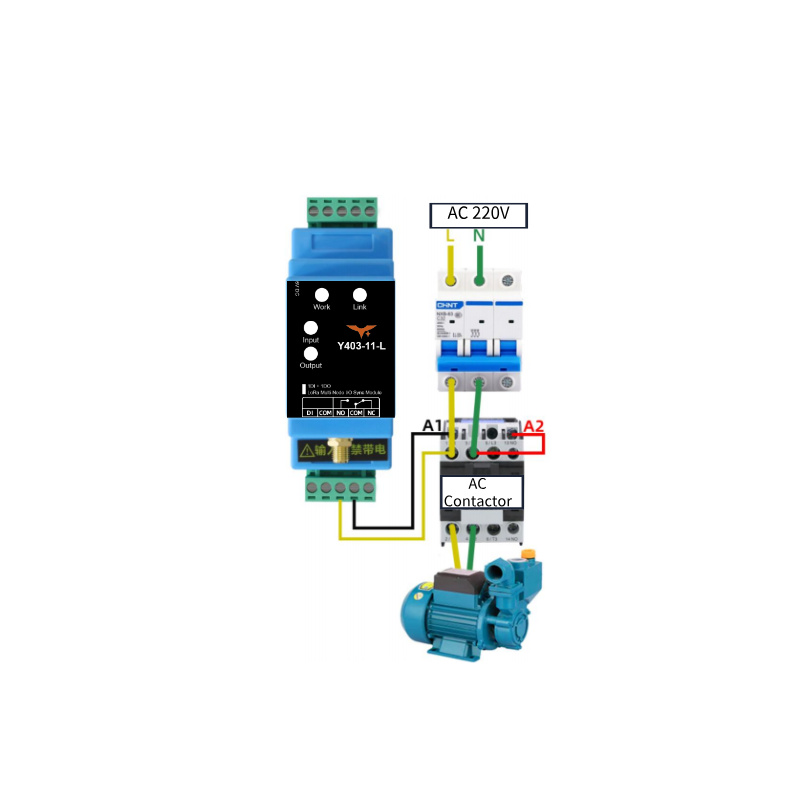
Connecting to AC Contactor
If controlling a high-power device (above 1KW, pure resistive load), a contactor is required. Refer to the following wiring diagram for a 220V AC contactor:
6. Precautions
The wireless linkage switch controller Y403-11-L is a half-duplex communication device. In complex environments, signal transmission time over the air is uncertain, making it unsuitable for applications requiring high real-time performance.
Antenna operating frequency range: (398\sim 525\mathrm{MHz}). Operating outside this range will affect transmission and reception performance.
When in use, ensure the antenna connector is tightly screwed. Place the antenna in an open area, vertically oriented, approximately 2 meters above the ground, and keep it away from large metal equipment.
- Manufacturer: Hunan Yanji Tech Co.,Ltd
- Address: Room 21014, Unit 1, Fudixingguang plaza, Yuhua district Yingxin road, Changsha, Hunan, P.R. China
- Email: hi@yengear.com
- Website: www.yengear.com