Appearance
Y301-600/800/G00 Digital Input Module Specification
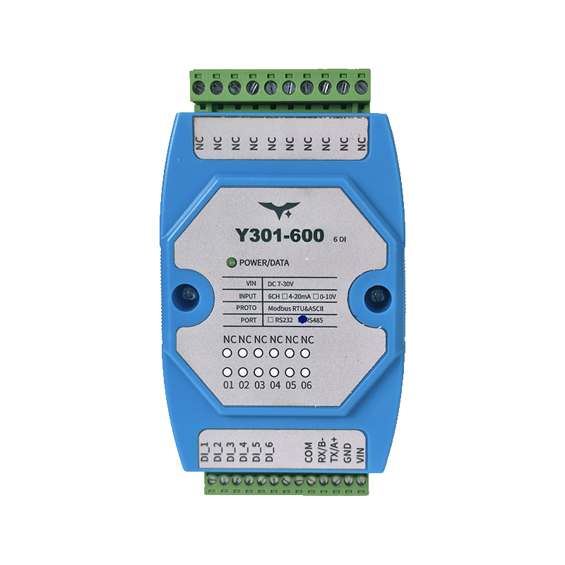
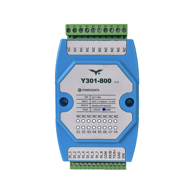
| Y301-600 | Y301-800 | Y301-G00 |
|---|---|---|
 |  | |
Manufacturer: Hunan Yanji Tech Co.,Ltd
Address: Room 21014, Unit 1, Fudixingguang Plaza, Yuhua District Yingxin Road, Changsha, Hunan, P.R. China
Email: hi@yanjiiot.com
Website: www.yanjiiot.com
Document Control
| Item | Detail |
|---|---|
| Version | V1.0.0 |
| Release Date | November 2025 |
| Product Category | Serial DI Module |
Table of Contents
- Overview
- Ordering Information
- Key Features
- Technical Specifications
- Interface & Pin Description
- Wiring & Installation
- Mechanical & Environmental
- Configuration & Debugging
- Diagnostics & FAQ
1. Overview
Y301-600/800/G00 are dedicated Modbus-RTU digital input aggregators derived from the DAM0800DI-YD hardware platform. They provide isolated optocoupler inputs for dry or wet contacts and deliver plug-and-play signal acquisition to PLCs, SCADA systems, and telemetry terminals.
| Model | Digital Inputs | Communication | Typical Use |
|---|---|---|---|
| Y301-600 | 6 opto-isolated | RS485 or RS232 | Compact cabinet retrofits |
| Y301-800 | 8 opto-isolated | RS485 or RS232 | Multi-loop monitoring |
| Y301-G00 | 16 opto-isolated | RS485 or RS232 | High-density signal aggregation |
Positioning Highlights
- 120 × 70 × 35 mm DIN-rail enclosure with single LED power indicator
- Industrial temperature (-40 °C ~ +85 °C) and 7–30 V DC supply range
- Standard Modbus-RTU/ASCII protocol with configurable slave address (0–255) and baud rate
- Supports dry contacts or 3.3–24 V wet inputs without external conditioning
2. Ordering Information
2.1 Model Naming
Y301-XYZ-IF
- XYZ: 600 = 6DI, 800 = 8DI, G00 = 16DI
- IF: RS485 (default) or RS232 interface
2.2 SKU Matrix
| SKU | Interface | Description |
|---|---|---|
| Y301-600-RS485 | RS485 | 6-channel DI module for multi-drop |
| Y301-600-RS232 | RS232 | 6-channel DI module for point-to-point |
| Y301-800-RS485 | RS485 | 8-channel DI module |
| Y301-800-RS232 | RS232 | 8-channel DI module |
| Y301-G00-RS485 | RS485 | 16-channel DI aggregator |
| Y301-G00-RS232 | RS232 | 16-channel DI aggregator |
2.3 Standard Package
1× Y301 module, online quick-start guide, warranty leaflet. Optional accessories: USB–RS485 converter, DIN clips, fused DC power supply, shielded twisted-pair cabling kit.
3. Key Features
- Isolated Inputs – Optocoupler front-end tolerates dry contacts or 3.3–24 V wet signals, suitable for sensors, buttons, and PLC outputs.
- Flexible Addressing – Software-configurable device address (0–255) with broadcast support (0xFE) for single-node commissioning.
- Wide Supply Range – 7–30 V DC input with reverse-polarity protection and single LED health indicator.
- Modbus Compatibility – Responds to standard function codes (01/02/03/05/15) and shares register conventions with the broader Y301 family.
- Software Ecosystem – Bundled JYDAM tool offers parameter read/write, DI status display, command generation, and Excel export.
- Industrial Durability – -40 °C to +85 °C, 35 mm DIN mounting, shielded RS485 wiring up to 1200 m @ 9600 bps.
4. Technical Specifications
4.1 Electrical & Environmental
| Parameter | Specification |
|---|---|
| Supply Voltage | DC 7–30 V |
| Typical Power Draw | <1 W (@12 V) |
| Power Indicator | 1 × LED |
| Operating Temperature | -40 °C ~ +85 °C |
| Humidity | 5–95 % RH, non-condensing |
| Dimensions | 120 × 70 × 35 mm |
| Mounting | 35 mm DIN rail |
| Weight | ≈60 g |
4.2 Digital Inputs
| Item | Y301-600 | Y301-800 | Y301-G00 |
|---|---|---|---|
| Channels | 6 | 8 | 16 |
| Type | Opto-isolated dry/wet contact | ||
| Wet Voltage Range | 3.3–24 V DC | ||
| Input Current | <5 mA/channel | ||
| Sampling Rate | 100 Hz | ||
| Indicators | Shared via software status |
4.3 Communication
| Parameter | Specification |
|---|---|
| Interface | RS485 (A/B/GND) or RS232 (TX/RX/GND) |
| Protocol | Modbus RTU / ASCII slave |
| Baud Rate | 2400, 4800, 9600 (default), 19200, 38400 bps |
| Data Format | 8 N 1 (default), configurable via software |
| Slave Address | 0–255 (default 1); broadcast address 254 |
| Bus Capacity | Up to 32 RS485 nodes without repeater |
5. Interface & Pin Description
| Terminal | Description |
|---|---|
| VIN | Power supply positive (7–30 V DC) |
| GND | Power supply negative |
| DIx | Individual digital input channels (x = 1…n) |
| COM | Common reference for DI signals |
| A / 485+ | RS485 positive |
| B / 485- | RS485 negative |
| TX | RS232 transmit (for RS232 SKU) |
| RX | RS232 receive (for RS232 SKU) |
| GND (COM) | Communication ground |
Communication Protocols: Supports both Modbus RTU and ASCII framing on RS485/RS232 links.
6. Wiring & Installation
6.1 Wet (Active) Inputs
- Connect sensor positive output to the target DI channel.
- Connect sensor negative to COM.
- Supported voltage: 3.3–24 V DC.
- Typical sources: proximity sensors, PLC transistor outputs, photoelectric sensors.
6.2 Dry (Passive) Inputs
- Bridge VIN (or external excitation) through the switch contact into the DI channel.
- Reference the opposite end of the contact to COM.
- Typical sources: mechanical switches, relay contacts, limit switches, door sensors.
6.3 RS485 Daisy Chain
- Tie all A terminals together and all B terminals together; share signal ground.
- Terminate both ends of the bus with 120 Ω resistors.
- Use shielded twisted pair and keep stubs <1 m.
- Max segment length: 1200 m at 9600 bps with 32 nodes.
6.4 RS232 Point-to-Point
- Module TX → Host RX, Module RX → Host TX, GND ↔ GND.
- Recommended cable length ≤15 m.
7. Mechanical & Environmental
| Item | Specification |
|---|---|
| Dimensions | 120 × 70 × 35 mm |
| Mounting | 35 mm DIN rail |
| Enclosure | UL94 V-0 flame-retardant plastic |
| Protection | IP20 |
| Weight | ≈60 g |
Clearance: keep ≥20 mm above/below, ≥10 mm at the sides, and ≥50 mm at the front for wiring. Avoid routing low-level inputs parallel to high-voltage cabling.
8. Configuration & Debugging
7.1 JYDAM Tool Highlights
| Function Block | Description |
|---|---|
| Communication Settings | Select serial/IP channel, baud rate, refresh interval. |
| DI Monitor | View live DI status, generate query frames, rename channels. |
| Configuration | Read/write baud rate, offset address, working mode, auto-report settings. |
| Command Area | Auto-build Modbus frames for DI reads and parameter writes. |
| Debug Console | Manual hex command injection for advanced testing. |
Commissioning Steps
- Select the correct COM port (or TCP bridge) and set baud rate (default 9600).
- Use broadcast address 254 to discover the module, then assign a unique address.
- Verify DI status updates in the DI Monitor pane.
- Export logs/Excel data if needed for acceptance tests.
9. Diagnostics & FAQ
| Issue | Probable Cause | Recommended Action |
|---|---|---|
| RS232 link unresponsive | TX/RX crossed incorrectly | Use straight-through wiring: RX↔RX, TX↔TX, GND↔GND as per Chinese manual guidance. |
| DI only turns on, never off | Address mismatch or missing response | Confirm slave address, monitor return frames, and re-check wiring/converter. |
| Multiple RS485 nodes misbehave | Broadcast address still in use | Assign unique addresses; avoid 0xFE when more than one module is online. |
For extended troubleshooting, refer to the Technical Manual.
- Manufacturer: Hunan Yanji Tech Co.,Ltd
- Address: Room 21014, Unit 1, Fudixingguang Plaza, Yuhua District Yingxin Road, Changsha, Hunan, P.R. China
- Email: hi@yanjiiot.com
- Website: www.yanjiiot.com