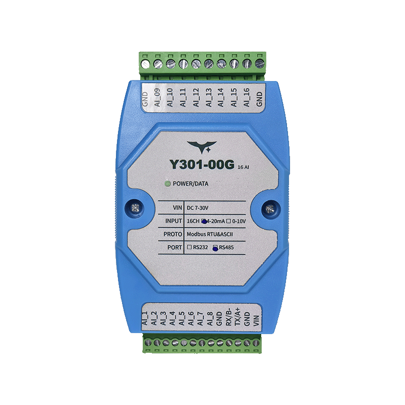
Appearance
Y301-006/008/00G Analog Input Module Specification
| Y301-006 | Y301-008 | Y301-00G |
|---|---|---|
 | | |
Manufacturer: Hunan Yanji Tech Co.,Ltd
Address: Room 21014, Unit 1, Fudixingguang Plaza, Yuhua District Yingxin Road, Changsha, Hunan, P.R. China
Email: hi@yanjiiot.com
Website: www.yanjiiot.com
Document Control
| Item | Detail |
|---|---|
| Version | V1.0.0 |
| Release Date | November 2025 |
| Product Category | Serial Analog Input Module |
Table of Contents
- Overview
- Ordering Information
- Key Features
- Technical Specifications
- Interface & Pin Description
- Wiring Guidance
- Mechanical & Environmental
- Communication & Configuration
- Diagnostics & FAQ
1. Overview
The Y301-006/008/00G family are multi-channel analog input concentrators based on the DAM1600AI-YD hardware platform. They acquire 4–20 mA or 0–10 V signals over Modbus-RTU/ASCII links and stream normalized values to PLCs, SCADA systems, or edge controllers.
| Model | Analog Inputs | Interface Options | Typical Scenario |
|---|---|---|---|
| Y301-006 | 6 channels | RS485 / RS232 | Compact HVAC or OEM skids |
| Y301-008 | 8 channels | RS485 / RS232 | Building automation, lab rigs |
| Y301-00G | 16 channels | RS485 / RS232 | High-density telemetry panels |
Positioning Highlights
- 12-bit A/D converter with linear scaling (
actual value = register × 0.001) - 7–30 V DC wide-range supply with single LED health indicator
- DIN-rail (35 mm) housing sized 100 × 70 × 35 mm
- Broadcast-friendly commissioning (default address 0, broadcast 254)
2. Ordering Information
2.1 Model Naming
Y301-00X-IF
- 00X – 006 (6 AI), 008 (8 AI), 00G (16 AI)
- IF – RS485 (multi-drop) or RS232 (point-to-point)
2.2 SKU Matrix
| SKU | Interface | Description |
|---|---|---|
| Y301-006-RS485 | RS485 | 6-channel analog concentrator |
| Y301-006-RS232 | RS232 | 6-channel point-to-point module |
| Y301-008-RS485 | RS485 | 8-channel analog concentrator |
| Y301-008-RS232 | RS232 | 8-channel point-to-point module |
| Y301-00G-RS485 | RS485 | 16-channel analog concentrator |
| Y301-00G-RS232 | RS232 | 16-channel point-to-point module |
2.3 Standard Package
Module, online quick reference card, warranty leaflet. Optional accessories: shielded twisted pair cable, USB–RS485 converter, 12/24 V DIN power supply.
3. Key Features
- 16-Channel AI Core – Scalable 6/8/16-channel variants with per-channel LED indication.
- Dual Communication Ports – RS485 multi-drop (A/B/GND) and RS232 (TX/RX/GND) versions share identical firmware.
- Flexible Signal Support – Accepts 4–20 mA loop or 0–10 V voltage sources, with wiring templates for 2/3/4-wire sensors.
- Modbus Compliance – Function code 0x04 for AI readings, 0x03/0x06 for address and baud configuration.
- Industrial Build – -40 °C to +85 °C, 5–95 % RH, reverse-polarity tolerant 7–30 V input.
- JYDAM Tooling – Free diagnostic utility for real-time curves, Excel export, offset/baud adjustments, and broadcast discovery.
4. Technical Specifications
4.1 Electrical & Environmental
| Parameter | Specification |
|---|---|
| Supply Voltage | DC 7–30 V |
| Typical Power Draw | <1.5 W |
| Indicators | 1 × POWER LED, per-channel AI LEDs |
| Operating Temperature | -40 °C ~ +85 °C |
| Humidity | 5–95 % RH (non-condensing) |
| Dimensions | 100 × 70 × 35 mm |
| Mounting | 35 mm DIN rail |
| Weight | ≈60 g |
4.2 Analog Inputs
| Item | Specification |
|---|---|
| Channels | 6 / 8 / 16 (model dependent) |
| ADC Resolution | 12-bit |
| Input Modes | 4–20 mA (current), 0–10 V (voltage) |
| Accuracy | ±0.5 % F.S. typical |
| Sampling | Sequential scan, register updated continuously |
| Scaling | Actual value (engineering units) = register × 0.001 |
4.3 Communication
| Parameter | Specification |
|---|---|
| Interface | RS485 (2-wire half-duplex) or RS232 |
| Protocol | Modbus RTU / ASCII |
| Baud Rates | 2400, 4800, 9600 (default), 19200, 38400 bps |
| Slave Address | 0–255 (default offset 0, broadcast 254) |
| Cable Length | RS485 up to 1200 m @ 9600 bps |
5. Interface & Pin Description
| Terminal | Description |
|---|---|
| VIN | 7–30 V DC positive |
| GND | 0 V return and COM reference |
| AI1…AI16 | Analog input positives (model dependent) |
| COM | Analog input negative for all channels |
| A / 485+ | RS485 positive differential line |
| B / 485- | RS485 negative differential line |
| TX | RS232 transmit (for RS232 SKU) |
| RX | RS232 receive (for RS232 SKU) |
- Indicator LEDs: POWER plus one LED per AI channel reflecting live sampling.
- V_out Pin: Reserved/not used according to the Chinese manual.
6. Wiring Guidance
6.1 Two-Wire (Loop-Powered) Sensors
- Supply sensor from external 24 V loop.
- Insert module AI+ in series on the return leg.
- Tie sensor negative to COM.
6.2 Three-Wire Transmitters
- Share 24 V+ to both transmitter and VIN if required.
- Connect transmitter signal output to AI+.
- Join transmitter ground to COM.
6.3 Four-Wire Transmitters or Voltage Sources
- Route sensor Vout to AI+.
- Tie sensor ground to COM.
- Keep cable shields bonded at one end only; maintain separation from high-voltage conductors.
Notes
- Use shielded twisted pair for RS485 and analog loops.
- Do not connect both voltage and current outputs to the same channel simultaneously.
- Maintain <1 m stubs on RS485 buses and terminate ends with 120 Ω.
7. Mechanical & Environmental
| Item | Specification |
|---|---|
| Dimensions | 100 × 70 × 35 mm |
| Mounting | 35 mm DIN rail |
| Enclosure | UL94 V-0 flame-retardant plastic |
| Protection | IP20 |
| Weight | ≈60 g |
Maintain ≥20 mm clearance above/below, ≥10 mm at the sides, and ≥50 mm at the front for wiring. Keep analog harnesses separate from high-voltage cabling to minimize interference.
8. Communication & Configuration
- Addressing: Default offset = 0 (broadcast only). Set a unique address (1–255) via holding register 4×1003 before deploying multiple nodes.
- Baud Rate: Holding register 4×1001 accepts enumerated values (0–5) covering 2400–38400 bps; restart after updates.
- Protocol Selection: Register 4×1002 toggles RTU/ASCII; RTU is recommended for most deployments.
- JYDAM Workflow:
- Connect via USB–RS485 or direct RS232.
- Select product model, set serial parameters, and open port.
- Use broadcast address 254 to read the current slave ID.
- Confirm DI/AI refresh on-screen; export Excel data as needed.
9. Diagnostics & FAQ
| Issue | Cause | Resolution |
|---|---|---|
| No response over RS232 | TX/RX swapped or wrong baud | Wire RX↔RX, TX↔TX, GND↔GND; default 9600 bps. |
| Multiple devices echo simultaneously | All units left at broadcast address 254 | Assign unique addresses (register 4×1003) before sharing a bus. |
| Readings stuck at zero | Channel not wired or current loop open | Verify AI+/COM wiring, ensure loop power, confirm sensor output. |
| Readings saturated | Voltage mode but 4–20 mA source connected (or vice versa) | Match wiring to the correct mode; use external shunt for current-to-voltage conversions if required. |
| Noise or drift | Poor grounding or shared supply noise | Use shielded cable, single-point COM reference, and isolate sensor supply. |
For Modbus command listings, error codes, and advanced troubleshooting, see the Technical Manual.