Appearance
Y301-0004/0006/0008 Analog Output Module Specification
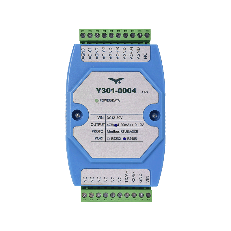
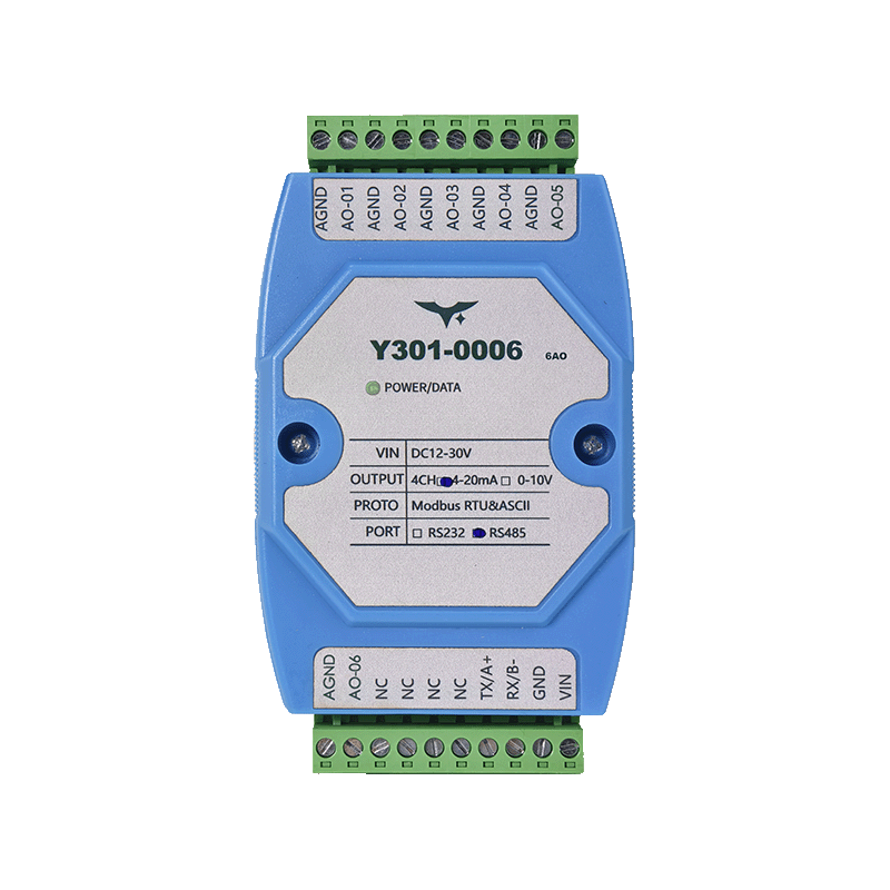
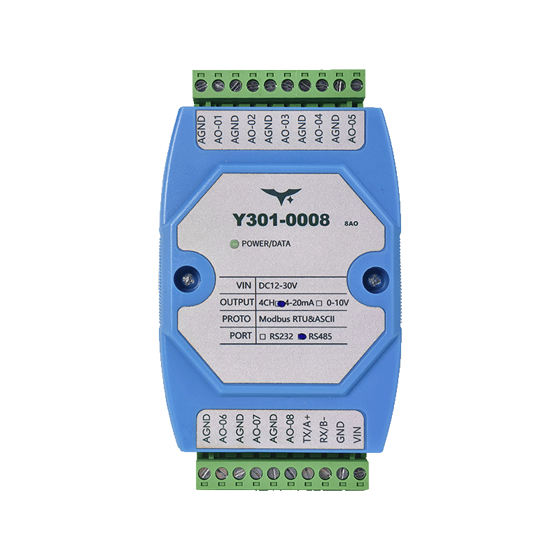
| Y301-0004 | Y301-0006 | Y301-0008 |
|---|---|---|
 |  |  |
Manufacturer: Hunan Yanji Tech Co.,Ltd
Address: Room 21014, Unit 1, Fudixingguang Plaza, Yuhua District Yingxin Road, Changsha, Hunan, P.R. China
Email: hi@yanjiiot.com
Website: www.yanjiiot.com
Document Control
| Item | Detail |
|---|---|
| Version | V1.0.0 |
| Release Date | November 2025 |
| Product Category | Serial Analog Output Module |
Table of Contents
- Overview
- Ordering Information
- Key Features
- Technical Specifications
- Interface & Pin Description
- Wiring Guidance
- Communication & Configuration
- Diagnostics & FAQ
1. Overview
Y301-0004/0006/0008 are analog output concentrators derived from the DAM0800AO-YD platform. They provide deterministic Modbus-RTU/ASCII control of 0–10 V and/or 4–20 mA channels for PLCs, SCADA, building automation, and laboratory systems.
| Model | Analog Outputs | Interface Options | Typical Role |
|---|---|---|---|
| Y301-0004 | 4 AO | RS485 / RS232 | Small HVAC and OEM retrofits |
| Y301-0006 | 6 AO | RS485 / RS232 | Medium process skids |
| Y301-0008 | 8 AO | RS485 / RS232 | High-density analog drive |
Positioning Highlights
- 14-bit DAC with 0.001 V / 0.001 mA resolution
- Configurable 0–10 V and 4–20 mA outputs (jumper-selectable compatible version)
- RS485 optical isolation plus optional RS232 port
- Drop-in Modbus integration with address retention and power-fail memory
2. Ordering Information
2.1 Model Naming
Y301-000X-IF-SIGNAL
- 000X – 0004 (4 AO), 0006 (6 AO), 0008 (8 AO)
- IF – RS485 or RS232
- SIGNAL – Voltage-only, current-only, or compatible (0–10 V & 4–20 mA switchable via jumpers)
2.2 SKU Matrix
| SKU | Interface | Output Mode | Description |
|---|---|---|---|
| Y301-0004-RS485-V | RS485 | 0–10 V | 4-channel voltage driver |
| Y301-0004-RS232-I | RS232 | 4–20 mA | 4-channel current driver |
| Y301-0004-RS485-C | RS485 | 0–10 V / 4–20 mA (compatible) | Jumper-switchable hybrid |
| Y301-0006-RS485-C | RS485 | Compatible | 6-channel AO |
| Y301-0006-RS232-C | RS232 | Compatible | 6-channel AO |
| Y301-0008-RS485-C | RS485 | Compatible | 8-channel AO |
| Y301-0008-RS232-C | RS232 | Compatible | 8-channel AO |
Compatible SKUs use internal jumpers to convert between voltage and current per channel.
2.3 Standard Package
Module, quick reference leaflet, warranty card. Optional accessories: DIN-rail 24 V supply, USB–RS485 converter, shielded pigtail harness.
3. Key Features
- High-Resolution DAC – Native 14-bit engine ensures 0.001 V / 0.001 mA step size.
- Robust Output Stage – Directly drives 0–10 V voltage loops or 4–20 mA current loops with fault protection.
- Flexible Protocols – Modbus RTU, ASCII, and (via host gateway) Modbus TCP; addresses 1–255.
- Wide Supply & Isolation – 12–30 V DC input, optically isolated RS485, surge-tolerant design.
- Dropout Memory – Optional power-fail retention ensures analog outputs resume last value after restart.
- JYDAM Tool Chain – GUI tool for multi-channel write, batch setpoints, Excel logging, and auto-baud discovery.
4. Technical Specifications
4.1 Electrical & Environmental
| Parameter | Specification |
|---|---|
| Supply Voltage | DC 12–30 V |
| Typical Power | 11 mA @24 V (~0.26 W) |
| Isolation | RS485 opto-isolated |
| Operating Temperature | -40 °C ~ +85 °C |
| Humidity | 0–95 % RH, non-condensing |
| Dimensions | 100 × 70 × 35 mm |
| Weight | ≈170 g |
4.2 Analog Outputs
| Item | Specification |
|---|---|
| Channels | 4 / 6 / 8 (model dependent) |
| Resolution | 14-bit (0.001 V / 0.001 mA) |
| Voltage Mode | 0–10 V (0–10000 mV codes) |
| Current Mode | 4–20 mA (4000–20000 µA codes) |
| Accuracy | ±0.03 % FS @25 °C |
| Update Rate | Determined by Modbus write frequency |
| Memory | Optional power-off retention per channel |
4.3 Communication
| Parameter | Specification |
|---|---|
| Interface | RS485 (A/B/GND) or RS232 (TX/RX/GND) |
| Protocol | Modbus RTU / ASCII (TCP via external gateway) |
| Baud Rates | 2400, 4800, 9600 (default), 19200, 38400, 57600, 115200 (selectable) |
| Address Range | 1–255 (broadcast 254 reserved for commissioning) |
5. Interface & Pin Description
| Terminal | Description |
|---|---|
| VCC | 12–30 V DC positive |
| GND | 0 V return |
| RX / B- | RS232 RX or RS485 B- |
| TX / A+ | RS232 TX or RS485 A+ |
| AO1…AO8 | Analog output positives per channel |
| AGND | Common analog output return |
- Each AO+ pairs with AGND. For differential measurement, tie AGND to the receiving controller reference.
- RS485 shield should bond to GND at one end to avoid ground loops.
6. Wiring Guidance
6.1 Voltage Output (0–10 V)
- Connect AOx to the controller’s analog voltage input (+).
- Connect AGND to the controller’s analog ground.
- Ensure the receiving device input impedance ≥10 kΩ for best accuracy.
6.2 Current Output (4–20 mA)
- Place AOx in series with the receiving loop (AOx → PLC AI+, PLC AI− → AGND).
- Provide external loop power as required by the sensor or PLC input.
- Observe polarity; reverse wiring will force the output to zero.
6.3 General Practices
- Route analog lines away from relay or VFD cabling.
- For long runs, use twisted-shielded pair and terminate only at the controller end.
- Use separate returns (AGND) for analog loops to minimize ground noise.
7. Communication & Configuration
- Addressing: Default slave address = 1. Broadcast address 254 is used for initial discovery; address 0 is invalid.
- Baud Rate: Holding register 1000 stores the enumerated baud value (0–5). The same register applies to RS232 and RS485 ports.
- Parity & Stop Bits: Adjustable via bit-fields (per DAM0800AO PDF) when using JYDAM or custom Modbus writes.
- Setpoint Scaling: Output code =
Actual Value × 1000. Example: 5.000 V → write5000to the AO register. - Multi-Channel Writes: Use Modbus function 0x10 to update multiple AO channels synchronously, ensuring deterministic waveform generation.
8. Diagnostics & FAQ
| Issue | Probable Cause | Recommended Action |
|---|---|---|
| Analog output unresponsive | Wrong slave address or no Modbus acknowledgment | Verify offset register, watch for responses in JYDAM debug pane, inspect converter wiring. |
| Output saturates at 0 or max | Writing raw codes outside valid range (0–10000 or 4000–20000) | Clip writes to legal range; confirm voltage/current mode jumpers. |
| RS485 bus noisy | Missing shield/termination or mixed baud | Install 120 Ω terminators, common reference, ensure all nodes share baud/parity. |
| Power-up state incorrect | Dropout memory disabled | Enable power-fail retention via configuration (holding register) if last output must resume after restart. |
For Modbus register maps, command samples, and extended troubleshooting, refer to the Technical Manual.